
VIP member

XLCS cyclone sand removal machine (bell shaped sand tank)
XLCS cyclone sand removal machine (bell shaped sand tank)
Product details
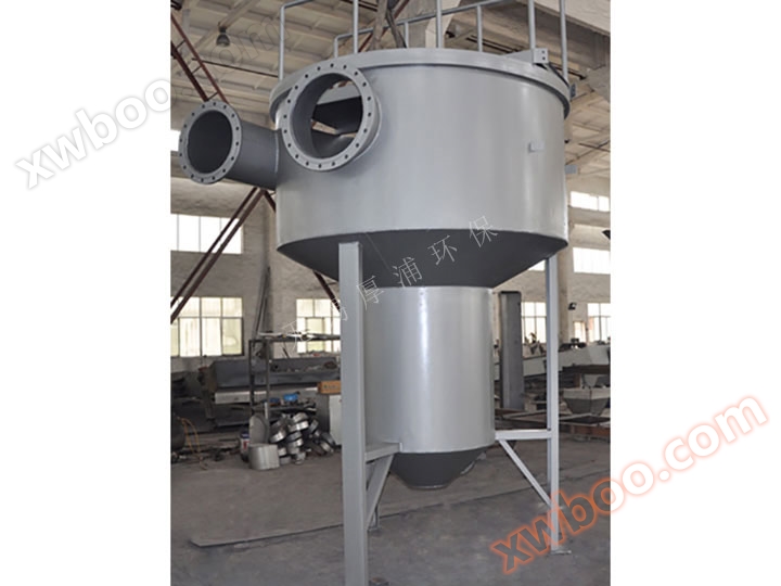
overview
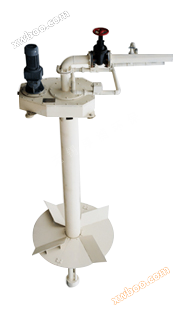
The bell shaped sand settling tank consists of an electric motor, a reducer, an impeller spindle, rotary blades, an air lifting and air flushing system, a sand suction pipe and a steel platform, a tank body (usually a concrete tank, users can choose a steel tank body), and the diameter and height of the rotary blades are customized according to the user's tank body.
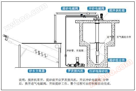
When the cyclone sand removal machine is running, the sand water mixture enters the bell shaped sand tank from the tangential direction, forming a cyclone. Under the drive of the driving device, the impeller of the stirring mechanism operates to control the flow rate and flow state of the sewage entering the pool.
Due to the upward inclination of the impeller blade slurry, the sewage in the pool will be accelerated in a spiral shape during rotation, forming a vortex flow state and generating attention force. At the same time, the sewage flow in the pool is separated from each other by the stirring shear force of the impeller blades. Relying on the self gravity of the sand and the centrifugal force of the vortex, the sand particles accelerate and settle along the pool wall in a spiral line, accumulate in the central sand hopper, and are lifted by air or pump before being discharged from the pool for further treatment. During this process, appropriate blade angles and linear velocity conditions allow the sand particles in the sewage to be washed away and maintain good settling effects. Organic matter and other small substances that originally adhered to the sand particles flow out of the cyclone sedimentation tank with the sewage and enter the subsequent process for further treatment. The sand and a small amount of sewage enter the sand water separator outside the tank, and after separation, the sand is discharged outside while the sewage flows back to the grid well.
Outline schematic diagram
The bell shaped sand settling tank consists of an electric motor, a reducer, an impeller spindle, rotary blades, an air lifting and air flushing system, a sand suction pipe and a steel platform, a tank body (usually a concrete tank, users can choose a steel tank body), and the diameter and height of the rotary blades are customized according to the user's tank body.
When the cyclone sand removal machine is running, the sand water mixture enters the bell shaped sand tank from the tangential direction, forming a cyclone. Under the drive of the driving device, the impeller of the stirring mechanism operates to control the flow rate and flow state of the sewage entering the pool.
Due to the upward inclination of the impeller blade slurry, the sewage in the pool will be accelerated in a spiral shape during rotation, forming a vortex flow state and generating attention force. At the same time, the sewage flow in the pool is separated from each other by the stirring shear force of the impeller blades. Relying on the self gravity of the sand and the centrifugal force of the vortex, the sand particles accelerate and settle along the pool wall in a spiral line, accumulate in the central sand hopper, and are lifted by air or pump before being discharged from the pool for further treatment. During this process, appropriate blade angles and linear velocity conditions allow the sand particles in the sewage to be washed away and maintain good settling effects. Organic matter and other small substances that originally adhered to the sand particles flow out of the cyclone sedimentation tank with the sewage and enter the subsequent process for further treatment. The sand and a small amount of sewage enter the sand water separator outside the tank, and after separation, the sand is discharged outside while the sewage flows back to the grid well.
Outline schematic diagram
|
|
Technical Characteristics
The cyclone sedimentation tank sand remover utilizes the dual effect of hydraulic cyclone and slight centrifugal force of impeller rotation to separate sediment from lighter suspended solids (organic matter), fully utilizing the hydraulic cyclone effect, maintaining a small footprint, short treatment residence time, good sand settling effect, strong sand water separability, and reliable sand removal (especially inorganic sand and gravel in sewage).
other
The cyclone sedimentation tank is generally a concrete structure. If the land occupation issue is considered in the design, it can be designed as a steel tank body with a compact structure and small land occupation area, depending on the specific situation.
structure parameters
Reference dimensions for the body of a bell shaped sedimentation tank
| model XLCS |
internet traffic (m/h) |
A/m | B/m | C/m | D/m | E/m | F/m | G/m | H/m | J/m | K/m | L/m |
| 180 | 180 | 1.83 | 1.0 | 0.30 | 0.61 | 0.3 | 1.40 | 0.30 | 0.30 | 0.20 | 0.80 | 1.10 |
| 360 | 396 | 2.13 | 0.38 | 0.76 | 1.40 | 0.30 | 0.30 | 0.30 | 1.10 | |||
| 720 | 648 | 2.43 | 0.45 | 0.90 | 1.35 | 0.40 | 0.30 | 0.40 | 1.15 | |||
| 1080 | 1116 | 3.05 | 0.61 | 1.2 | 1.35 | 0.45 | 0.30 | 0.45 | 1.35 | |||
| 1260 | 1908 | 3.65 | 1.5 | 0.75 | 1.5 | 0.4 | 1.55 | 0.60 | 0.51 | 0.58 | 1.45 | |
| 3240 | 3168 | 4.87 | 1.00 | 2.00 | 1.70 | 1.00 | 0.51 | 0.60 | 1.85 | |||
| 4680 | 4752 | 5.48 | 1.10 | 2.20 | 2.20 | 1.00 | 0.61 | 0.63 | 1.85 | |||
| 6300 | 6300 | 5.8 | 1.20 | 2.40 | 2.20 | 1.30 | 0.75 | 0.70 | 1.95 | |||
| 7200 | 7920 | 6.1 | 1.20 | 2.40 | 2.50 | 1.30 | 0.89 | 0.75 | 1.95 |
Mixing system and gas extraction parameters
| model XLCS |
agitator | Pool Size | Sand extraction volume (L/S) |
blower | ||
| Impeller speed (r/min) | power (KW) |
Air volume (m/min) |
power (KW) |
|||
| 180 | 12 | 1.1 | See the table above | 1-1.2 | 1.43 | 1.5 |
| 360 | 1.2-1.8 | 1.79 | 2.2 | |||
| 720 | 1.8-3 | |||||
| 1080 | 3-5 | |||||
| 1260 | 1.5 | 5-9.8 | 2.03 | 3 | ||
| 3240 | 9.8-15 | 1.98 | 4 | |||
| 4680 | 15-22 | |||||
| 6300 | 22-28 | 2.01 | ||||
| 7200 | 28-30 | |||||
Online inquiry
-
Contacts
-
Company
-
Telephone
-
Email
-
WeChat
-
Verification Code
-
Message Content
-