
VIP member
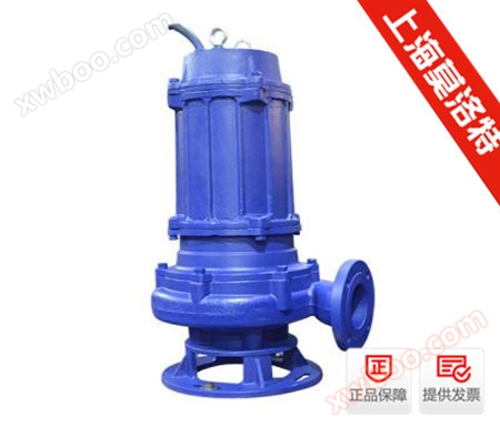
WQ type submersible unobstructed sewage pump
The WQ (QW) series submersible non clogging sewage pump has been developed based on the introduction of advanced foreign technology, with the joint ef
Product details
Overview of submersible sewage pumps
The WQ (QW) series submersible non clogging sewage pump has been developed based on the introduction of advanced foreign technology, with the joint efforts of our scientific research personnel and extensive solicitation of opinions from domestic pump experts. After multiple improvements, its performance indicators have reached the advanced level of similar foreign products after testing. Submersible sewage pump flow rate: 7-2400m3/h, head: 7-60m, etc. The submersible sewage pump is designed and manufactured into WL, YW, GW series products with the same performance parameters according to the medium used and the installation method.
Characteristics of submersible sewage pump products
1. By adopting a unique single or double disc wheel structure, the ability of dirt to pass through is greatly improved, which can effectively pass through the fiber material with a diameter of about 50% of the pump diameter and solid particles with a diameter of about 50% of the pump diameter.
2. The mechanical seal adopts hard and corrosion-resistant titanium tungsten material.
3. The overall structure is compact, the volume is small, the noise is low, the energy-saving effect is significant, the maintenance is convenient, and there is no need to build a pump room. It can work by diving in, greatly reducing the project cost.
4. A high-precision interference leakage detection sensor is installed in the sealed oil chamber, and a thermal sensor is embedded in the stator winding to automatically protect the water pump motor.
5. According to user needs, a fully automatic control cabinet can be equipped to automatically protect the pump from water leakage, electric leakage, overload, and overheating, improving the safety and reliability of the product.
6. The float switch can automatically control the start and stop of the pump according to the required liquid level changes, without the need for special supervision, making it extremely convenient to use.
7. The WQ series submersible sewage pump can be equipped with a dual rail automatic coupling installation system according to user needs, which brings greater convenience to installation and maintenance, and people do not have to enter the sewage pit for this.
8. It can be used within the full head without overloading the motor.
9. There are two different installation methods for submersible sewage pumps: fixed automatic coupling installation system and mobile free installation system.
Structural diagram of submersible sewage pump

Main purpose of submersible sewage pump
Submersible sewage pumps are suitable for conveying granular sewage and waste in industries such as chemical, petroleum, pharmaceutical, mining, paper industry, cement plants, steel mills, power plants, coal processing industry, as well as urban sewage treatment plant drainage systems, municipal engineering, construction sites, etc. Submersible sewage pumps can also be used to pump clean water and corrosive media.
Installation method of submersible sewage pump
The indoor sewage tank (collection pit) sewage pump adopts three forms of installation: mobile installation (flexible hose) (single pump), fixed installation (hard pipe) (single pump, double pump), and fixed installation with automatic coupling device (single pump, double pump). The flexible hose connection mobile installation is limited to submersible sewage pumps with motor power N ≤ 7.5 kW and discharge pipes DN ≤ 100 mm. The outdoor sewage tank only adopts one form of fixed installation with automatic coupling device (double pump). The installation method of the sewage pump used for the drainage pit of the fire elevator should adopt 2 sets of hard pipe connected fixed type or 2 sets of fixed self coupling type, and the effective volume of the collection well should not be less than 2.0 m3, and the rated flow rate of the sewage pump should not be less than 36 m3/h.
Conditions for use of submersible sewage pumps
1. The medium temperature does not exceed 60 ℃, the medium density is 11.3 × 10³kg/m3, and the pH value is within the range of 59.
2. For pumps without internal self circulating cooling systems, the exposed liquid level of the motor part shall not exceed 1/2.
3. The main component material of this pump is cast iron, so it cannot be used for pumping highly corrosive liquids.
Model meaning
For example: 40QW (WQ) 15-30-2.2
40 caliber (mm)
QW (WQ) - Submersible sewage pump
15- Flow rate (m3/h)
30 Head (m)
2.2- Equipped motor power (kw)
| Model number | Caliber (mm) |
Traffic volume (m3/h) |
Head lift (m) |
Power (kw) |
Rotational speed (r/min) |
Efficiency (%) |
| QW25-8-15-1.1 | 25 | 8 | 15 | 1.1 | 2825 | 38.5 |
| QW32-12-15-1.1 | 32 | 12 | 15 | 1.1 | 2825 | 40 |
| QW40-15-15-1.5 | 40 | 15 | 15 | 1.5 | 2840 | 45.1 |
| QW40-15-30-2.2 | 40 | 15 | 30 | 2.2 | 2840 | 48 |
| QW50-20-7-0.75 | 50 | 20 | 7 | 0.75 | 1390 | 54 |
| QW50-10-10-0.75 | 50 | 10 | 10 | 0.75 | 1390 | 56 |
| QW50-20-15-1.5 | 50 | 20 | 15 | 1.5 | 2840 | 55 |
| QW50-15-25-2.2 | 50 | 15 | 25 | 2.2 | 2840 | 56 |
| QW50-18-30-3 | 50 | 18 | 30 | 3 | 2880 | 58 |
| QW50-25-32-5.5 | 50 | 25 | 32 | 5.5 | 2900 | 53 |
| QW50-20-40-7.5 | 50 | 20 | 40 | 7.5 | 2900 | 55 |
| QW65-25-15-2.2 | 65 | 25 | 15 | 2.2 | 2840 | 52 |
| QW65-37-13-3 | 65 | 37 | 13 | 3 | 2880 | 55 |
| QW65-25-30-4 | 65 | 25 | 30 | 4 | 2890 | 58 |
| QW65-30-40-7.5 | 65 | 30 | 40 | 7.5 | 2900 | 56 |
| QW65-35-50-11 | 65 | 35 | 50 | 11 | 2930 | 60 |
| QW65-35-60-15 | 65 | 35 | 60 | 15 | 2930 | 63 |
| QW80-40-7-2.2 | 80 | 40 | 7 | 2.2 | 1420 | 52 |
| QW80-43-13-3 | 80 | 43 | 13 | 3 | 2880 | 50 |
| QW80-40-15-4 | 80 | 40 | 15 | 4 | 2890 | 57 |
| QW80-65-25-7.5 | 80 | 65 | 25 | 7.5 | 2900 | 56 |
| QW100-80-10-4 | 100 | 80 | 10 | 4 | 1440 | 62 |
| QW100-110-10-5.5 | 100 | 110 | 10 | 5.5 | 1440 | 66 |
| QW100-100-15-7.5 | 100 | 100 | 15 | 7.5 | 1440 | 67 |
| QW100-85-20-7.5 | 100 | 85 | 20 | 7.5 | 1440 | 68 |
| QW100-100-25-11 | 100 | 100 | 25 | 11 | 1460 | 65 |
| QW100-100-30-15 | 100 | 100 | 30 | 15 | 1460 | 66 |
| QW100-100-35-18.5 | 100 | 100 | 35 | 18.5 | 1470 | 65 |
| QW125-130-15-11 | 125 | 130 | 15 | 11 | 1460 | 62 |
| QW120-130-20-15 | 125 | 130 | 20 | 15 | 1460 | 63 |
| QW150-145-9-7.5 | 150 | 145 | 9 | 7.5 | 1440 | 63 |
| QW150-180-15-15 | 150 | 180 | 15 | 15 | 1460 | 65 |
| QW150-180-20-18.5 | 150 | 180 | 20 | 18.5 | 1470 | 75 |
| QW150-180-25-22 | 150 | 180 | 25 | 22 | 1470 | 76 |
| QW150-130-30-22 | 150 | 130 | 30 | 22 | 1470 | 75 |
| QW150-180-30-30 | 150 | 180 | 30 | 30 | 1470 | 73 |
| QW150-200-30-37 | 150 | 200 | 30 | 37 | 1480 | 70 |
| QW200-300-7-11 | 200 | 300 | 7 | 11 | 970 | 73 |
| QW200-250-11-15 | 200 | 250 | 11 | 15 | 970 | 74 |
| QW200-400-10-22 | 200 | 400 | 10 | 22 | 1470 | 76 |
| QW200-400-13-30 | 200 | 400 | 13 | 30 | 1470 | 73 |
| QW200-250-15-18.5 | 200 | 250 | 15 | 18.5 | 1470 | 72 |
| QW200-300-15-22 | 200 | 300 | 15 | 22 | 1470 | 73 |
| QW200-250-22-30 | 200 | 250 | 22 | 30 | 1470 | 71 |
| QW200-350-25-37 | 200 | 350 | 25 | 37 | 1980 | 75 |
| QW200-400-30-55 | 200 | 400 | 30 | 55 | 1480 | 70 |
| QW250-600-9-30 | 250 | 600 | 9 | 30 | 980 | 74 |
| QW250-600-12-37 | 250 | 600 | 12 | 37 | 1480 | 78 |
| QW250-600-15-45 | 250 | 600 | 15 | 45 | 1480 | 75 |
| QW250-600-20-55 | 250 | 600 | 20 | 55 | 1480 | 73 |
| QW250-600-25-75 | 250 | 600 | 25 | 75 | 1480 | 73 |
| QW300-800-12-45 | 300 | 800 | 12 | 45 | 980 | 76 |
| QW300-500-15-45 | 300 | 500 | 15 | 45 | 980 | 70 |
| QW300-800-15-55 | 300 | 800 | 15 | 55 | 980 | 73 |
| QW300-600-20-55 | 300 | 600 | 20 | 55 | 980 | 75 |
| QW300-800-20-75 | 300 | 800 | 20 | 75 | 980 | 78 |
| QW300-950-20-90 | 300 | 950 | 20 | 90 | 980 | 80 |
| QW300-1000-25-110 | 300 | 1000 | 25 | 110 | 980 | 82 |
| QW350-1100-10-55 | 350 | 1100 | 10 | 55 | 980 | 84.5 |
| QW350-1500-15-90 | 350 | 1500 | 15 | 90 | 980 | 82.5 |
| QW350-1200-18-90 | 350 | 1200 | 18 | 90 | 980 | 83.1 |
| QW350-1100-28-132 | 350 | 1100 | 28 | 132 | 740 | 83.2 |
| QW350-1000-36-160 | 350 | 1000 | 36 | 160 | 740 | 78.5 |
| QW400-1500-10-75 | 400 | 1500 | 10 | 75 | 980 | 82.1 |
| QW400-2000-15-132 | 400 | 2000 | 15 | 132 | 740 | 85.5 |
| QW400-1700-22-160 | 400 | 1700 | 22 | 160 | 740 | 82.1 |
| QW400-1500-26-160 | 400 | 1500 | 26 | 160 | 740 | 83.5 |
| QW400-1700-30-200 | 400 | 1700 | 30 | 200 | 740 | 83.5 |
| QW400-1800-32-250 | 400 | 1800 | 32 | 250 | 740 | 82.1 |
| QW500-2500-10-110 | 500 | 2500 | 10 | 110 | 740 | 82 |
| QW500-2600-15-160 | 500 | 2600 | 15 | 160 | 740 | 83 |
| QW500-2400-22-220 | 500 | 2400 | 22 | 220 | 740 | 84 |
| QW500-2600-24-250 | 500 | 2600 | 24 | 250 | 740 | 82 |
Installation condition requirements
1. Before installation, carefully check whether there are any hard objects inside the pump body to avoid damaging the impeller and pump body during operation.
2. During installation, pipeline management should not be added to the pump to prevent deformation and affect normal operation.
3. Tighten the anchor bolts to prevent vibration during start-up from affecting the performance of the pump.
4. Install regulating valves on the inlet and outlet pipelines of the pump, and install pressure gauges near the pump outlet to control the pump's operation within rated conditions and ensure its normal use.
Online inquiry
-
Contacts
-
Company
-
Telephone
-
Email
-
WeChat
-
Verification Code
-
Message Content
-