
VIP member
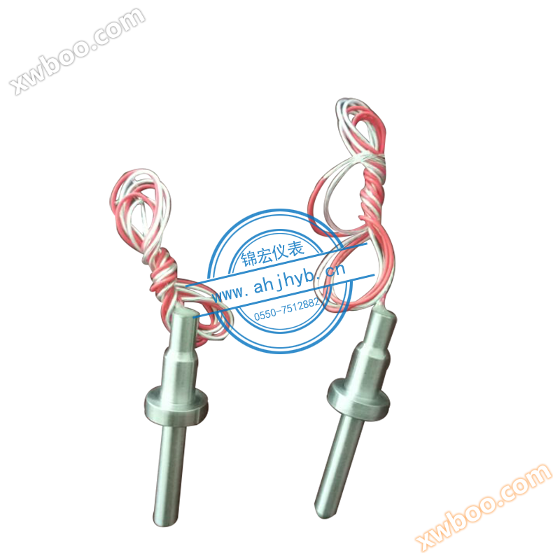
Temperature compensation thermistor for flowmeter
Thermistor is a primary component that converts temperature changes into changes in resistance values. Typically, the resistance signal needs to be tr
Product details
Thermistor is a primary component that converts temperature changes into changes in resistance values. Typically, the resistance signal needs to be transmitted through leads to a computer control device or other primary instrument. Industrial thermal resistors are installed on the production site, and there is a certain distance between them and the temperature sensor room that controls the thermal resistor. Therefore, the leads of the thermal resistor will have a significant impact on the measurement results.
There are three main ways to lead wires for national standard thermal resistors
○ 1 Two wire system: The method of connecting a wire at each end of a thermal resistor to extract a resistance signal is called a two wire system: This lead method is simple, but due to the inevitable lead resistance r in connecting wires, the size of r is related to the material and length of the wire, so this lead method is only suitable for situations with low measurement accuracy
○ 2 Three wire system: The method of connecting one lead at the root of a thermal resistor and two leads at the other end is called the three wire system. This method is usually used in conjunction with an electric bridge to effectively eliminate the influence of lead resistance and is commonly used in industrial process control.
○ 3 Four wire system: The method of connecting two wires at each end of the root of the thermistor is called a four wire system, where two leads provide a constant current I to the thermistor, convert R into a voltage signal U, and then lead U to the secondary instrument through the other two leads. It can be seen that this lead method can completely eliminate the influence of lead resistance and is mainly used for high-precision temperature detection.
The thermal resistor adopts a three wire connection method. The use of a three wire system is to eliminate measurement errors caused by the resistance of connecting wires. This is because the circuit for measuring thermal resistance is usually an unbalanced bridge. As a bridge arm resistor of the electric bridge, the thermal resistor's connecting wire (from the thermal resistor to the central control room) also becomes a part of the bridge arm resistor. This part of the resistor is unknown and varies with the ambient temperature, causing measurement errors. Adopting a three wire system, one wire is connected to the power terminal of the bridge, and the other two wires are respectively connected to the bridge arm where the thermal resistance is located and the adjacent bridge arm, thus eliminating measurement errors caused by the resistance of the wire line.


Online inquiry
-
Contacts
-
Company
-
Telephone
-
Email
-
WeChat
-
Verification Code
-
Message Content
-