
VIP member
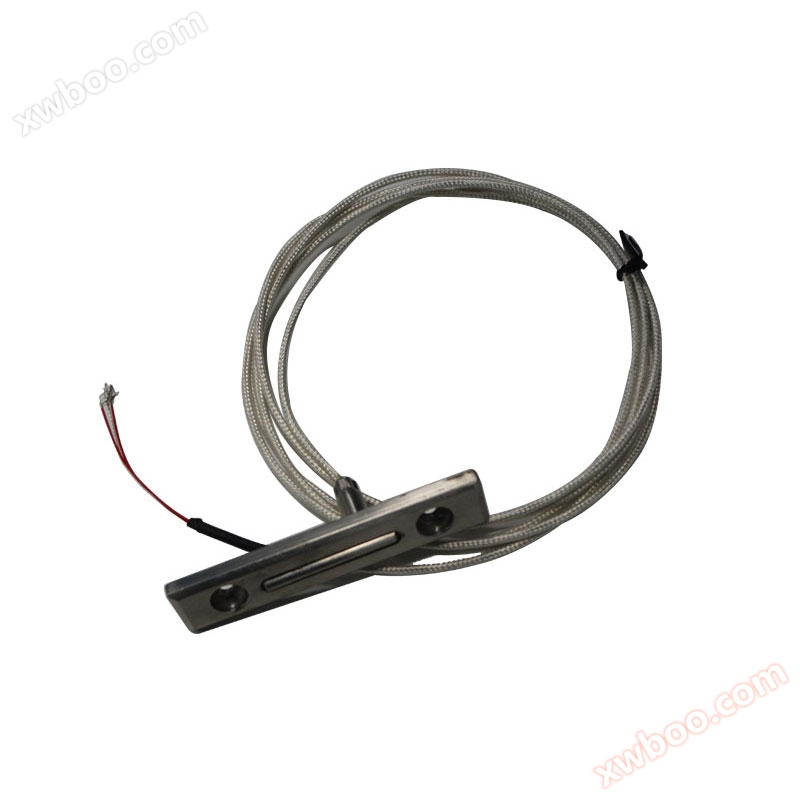
Special structure thermocouple thermal resistance
Hangzhou Yafei Automation Equipment Co., Ltd. is located by the beautiful West Lake and was founded in 1993. It is a professional manufacturer of ther
Product details
The working principle of armored thermocouples is to weld two conductors with different compositions at both ends to form a circuit. The direct temperature measuring end is called the measuring end, and the wiring end is called the reference end. When there is a temperature difference between the measuring end and the reference end, a thermal current will be generated in the circuit. When connected to a display instrument, the instrument will indicate the corresponding temperature value of the thermoelectric potential generated by the thermocouple.
The thermoelectric potential of the armored thermocouple will increase with the temperature rise at the measuring end. The magnitude of the thermoelectric potential is only related to the material of the armored thermocouple conductor and the temperature difference between the two ends, and is independent of the length and diameter of the thermoelectric electrode.
The structure of armored thermocouples is made up of conductors, insulated magnesium oxide, and 1Cr18Ni9Ti stainless steel protective tubes that have been drawn multiple times. Armored thermocouple products mainly consist of junction boxes, terminal blocks, and armored thermocouples, and are equipped with various installation and fixing devices.Armored thermocouples are divided into two types: insulated and shell connected.
Temperature measurement range and accuracy
|
Category |
code name |
graduation mark |
Outer diameter of casing mm |
Common temperature ℃ |
Maximum operating temperature ℃ |
Allowable deviation △ t |
|
|
Measurement range ℃ |
tolerance value |
||||||
|
Nickel chromium copper nickel |
WREK |
E |
≥Φ3 |
600 |
700 |
0~700 |
± 2.5 ℃ or ± 0.75% t |
|
Nickel chromium nickel silicon |
WRNK |
K |
≥Φ3 |
800 |
900 |
0~900 |
± 2.5 ℃ or ± 0.75% t |
|
Copper Copper Nickel |
WRCK |
T |
≥Φ3 |
350 |
400 |
<-200 |
Not specified |
|
-40~350 |
±0.75%t |
||||||
Note: 1) t is the value of the measured temperature.
2) The production of T-shaped dividing marks requires negotiation and ordering with the manufacturer.
Armored thermocouple thermal response time
When there is a step change in temperature, the output of the thermocouple changes to 50% of the step change, and the time required is called the thermal response time, represented by T0.5
The thermal response time of armored thermocouples shall not exceed the specifications in the following table:
|
Thermal response time T0.5S |
Shell type |
Insulated type |
|
Diameter of casing (min) |
||
|
2.0 |
0.4 |
0.5 |
|
3.0 |
0.6 |
1.2 |
|
4.0 |
0.8 |
2.5 |
|
5.0 |
1.2 |
4.0 |
|
6.0 |
2.0 |
6.0 |
|
8.0 |
4.0 |
8.0 |
insulation resistance
When the ambient air temperature is 20 ± 15 ℃ and the relative humidity is not greater than 80%, the insulation resistance value between the thermocouple wire and the outer sleeve of the insulated armored thermocouple should comply with the provisions in the table below.
|
Sleeve diameter mm |
Test voltage V-D.C |
Insulation resistance M Ω. m |
|
0.5~1.5 |
50±5 |
≥1000 |
|
>1.5 |
500±50 |
≥1000 |
Model Number
|
W |
R |
Specifications |
Content |
||||||
|
|
|
N |
|
Nickel chromium nickel silicon |
|||||
|
E |
|
Nickel chromium copper nickel |
|||||||
|
C |
|
Copper Copper Nickel |
|||||||
|
Temperature measuring element material |
Armored type |
- |
1 |
|
Non fixed device type |
||||
|
2 |
|
Fixed card sleeve thread |
|||||||
|
3 |
|
Movable card sleeve thread |
|||||||
|
4 |
|
Fixed card sleeve flange |
|||||||
|
5 |
|
Movable card sleeve flange |
|||||||
|
An pretend solid fixed form formula |
0 |
|
Insulated type |
||||||
|
2 |
|
Shell type |
|||||||
|
3 |
|
waterproof type |
|||||||
|
8 |
|
Handle type |
|||||||
|
8 |
|
Small junction box |
|||||||
|
9 |
|
With compensating wire |
|||||||
|
pick up line box form formula |
1 |
|
Insulated type |
||||||
|
2 |
|
Shell type |
|||||||
|
8 |
|
Shell type (handle type) |
|||||||
|
9 |
|
Insulated (handle type) |
|||||||
|
Workplace format |
3 |
3 pairs |
|||||||
|
4 |
4 pairs |
||||||||
|
5 |
5 pairs |
||||||||
|
6 |
6 pairs |
||||||||
|
many to formula |
|
||||||||
|
W |
R |
□ |
K |
- |
□ |
□ |
□ |
□ |
|
Standard specifications for outer diameter and nominal length of armored thermocouples
|
Armored thermocouple outer diameter dmm |
||||
|
Φ8 |
Φ6 |
Φ5 |
Φ4 |
Φ3 |
|
50 75 100 150 200 250 300 400 500 750 1000 |
50 75 100 150 200 250 300 400 500 750 1000 1250 1500 2000 |
50 75 100 150 200 250 300 400 500 750 1000 1250 1500 2000 2500 3000 4000 |
50 75 100 150 200 250 300 400 500 750 1000 1250 1500 2000 2500 3000 4000 5000 7500 1000 |
50 75 100 150 200 250 300 400 500 750 1000 1250 1500 2000 2500 3000 4000 5000 7500 1000 1500 |
Note: 1. The nominal L of the insulated armored thermocouple with a diameter of Φ 3mm shall not exceed 10000mm
2. Armored thermocouples with a diameter of d ≤ Φ 5mm and equipped with splash proof or waterproof junction boxes. The thermocouple is exposed from the equipment, and users must install auxiliary supports such as brackets to increase its rigidity, ensure fastening, and prevent the junction box from shaking and damaging the thermocouple due to vibration.
3. The armored thermocouple with a diameter of Φ 2mm must be ordered through negotiation with our factory.
□ Structural form
Installation fixed form
Fixed devices are designed for users to install. In addition to the absence of fixed devices, armored thermocouple fixing devices have four structural forms: fixed sleeve type, movable sleeve type, fixed flange type, and movable flange type. Fixed card sleeve type for users to fix at once; The movable card sleeve support can be fixed multiple times.
In order to meet the different requirements of welding structures and sizes for fixed flange plates in different industries, our factory has decided to add three different welding methods and different forms of sealed fixed flange installation plates. Please refer to the models in d=1-8 and Table 3 of the assembly thermocouple appendix for details.
Armored thermocouple free end (junction box) form
The junction box is used to connect the free end of thermocouples and display instruments. Currently, there are various structural forms including simple, splash proof, waterproof, handle type, small junction box, plug-in, and compensating wire type.
Card sleeve threaded joint
|
Armored thermocouple outer diameter d |
Φ8 |
Φ6 |
Φ5 |
(Φ4) |
Φ4 |
Φ3 |
Φ2 |
|
Fixed device code and size |
|||||||
|
M |
M16×1.5 |
M12×1.5 |
|||||
|
S |
22 |
19 |
|||||
Card sleeve flange
|
Armored thermocouple outer diameter d |
Φ8 |
Φ6 |
Φ5 |
(Φ4) |
Φ4 |
Φ3 |
Φ2 |
|
Fixed device code and size |
|||||||
|
D |
Φ60 |
Φ50 |
|||||
|
D0 |
Φ45 |
Φ36 |
|||||
|
D1 |
Φ24 |
Φ20 |
|||||
|
S |
22 |
19 |
|||||
|
d0 |
Φ9 |
Φ7 |
|||||
- Armored thermocouple without fixed device
|
name |
model |
graduation mark |
Workplace format |
|
Single nickel chromium copper nickel |
WREK-101 WREK-121 WREK-131 WREK-181 WREK-187 WREK-191 |
E (EA-2) ﹡ |
Insulated type |
|
WREK-102 WREK-122 WREK-132 WREK-182 WREK-188 WREK-192 |
Shell type |
||
|
Double branch nickel chromium copper nickel |
WREK2-121 WREK2-131 |
Insulated type |
|
|
WREK2-122 WREK2-132 |
Shell type |
||
|
Single nickel chromium nickel silicon |
WRNK-121 WRNK-131 WRNK-181 WRNK-187 WRNK-191 |
K (EU-2) ﹡ |
Insulated type |
|
WRNK-102 WRNK-122 WRNK-132 WRNK-182 WRNK-188 WRNK-192 |
Shell type |
||
|
Double branch nickel chromium nickel silicon |
WRNK2-121 WRNK2-131 |
Insulated type |
|
|
WRNK2-122 WRNK2-132 |
Shell type |
||
|
Single copper copper nickel |
WRCK-101 WRCK-121 WRCK-131 WRCK-181 WRCK-187 WRCK-191 |
T (CK)﹡ |
Insulated type |
|
WRCK-102 WRCK-122 WRCK-132 WRCK-182 WRCK-188 WRCK-192 |
Shell type |
||
|
Double copper copper nickel |
WRCK2-121 WRCK2-131 |
Insulated type |
|
|
WRCK2-122 WRCK2-132 |
Shell type |
Note: (1) Mark the "*" division mark for special specification ordering
(2) Outer diameter of casing dmm: Φ 2, Φ 3, Φ 4, Φ 5, Φ 6, Φ 8
- Fixed card sleeve threaded device armored thermocouple
|
name |
model |
graduation mark |
Workplace format |
|
Single nickel chromium copper nickel |
WREK-201 WREK-221 WREK-231 WREK-281 WREK-291 |
E (EA-2) ﹡ |
Insulated type |
|
WREK-202 WREK-222 WREK-232 WREK-282 WREK-292 |
Shell type |
||
|
Double branch nickel chromium copper nickel |
WREK2-221 WREK2-231 |
Insulated type |
|
|
WREK2-222 WREK2-232 |
Shell type |
||
|
Single nickel chromium nickel silicon |
WRNK-201 WRNK-221 WRNK-231 WRNK-281 WRNK-291 |
K (EU-2) ﹡ |
Insulated type |
|
WRNK-202 WRNK-222 WRNK-232 WRNK-282 WRNK-292 |
Shell type |
||
|
Double branch nickel chromium nickel silicon |
WRNK2-221 WRNK2-231 |
Insulated type |
|
|
WRNK2-222 WRNK2-232 |
Shell type |
||
|
Single copper copper nickel |
WRCK-201 WRCK-221 WRCK-231 WRCK-281 WRCK-291 |
T (CK)﹡ |
Insulated type |
|
WRCK-202 WRCK-222 WRCK-232 WRCK-282 WRCK-292 |
Shell type |
||
|
Double copper copper nickel |
WRCK2-221 WRCK2-231 |
Insulated type |
|
|
WRCK2-222 WRCK2-232 |
Shell type |
Note: (1) Mark the "*" division mark for special specification ordering
(2) Outer diameter of casing dmm: Φ 2, Φ 3, Φ 4, Φ 5, Φ 6, Φ 8
- Movable card sleeve threaded device armored thermocouple
|
name |
model |
graduation mark |
Workplace format |
|
Single nickel chromium copper nickel |
WREK-301 WREK-321 WREK-331 WREK-381 WREK-387 WREK-391 |
E (EA-2) ﹡ |
Insulated type |
|
WREK-302 WREK-322 WREK-332 WREK-382 WREK-388 |
Shell type |
||
|
Double branch nickel chromium copper nickel |
WREK2-321 WREK2-331 |
Insulated type |
|
|
WREK2-322 WREK2-332 |
Shell type |
||
|
Single nickel chromium nickel silicon |
WRNK-301 WRNK-321 WRNK-331 WRNK-391 WRNK-381 WRNK-387 |
K (EU-2) ﹡ |
Insulated type |
|
WRNK-302 WRNK-322 WRNK-332 WRNK-392 WRNK-382 WRNK-388 |
Shell type |
||
|
Double branch nickel chromium nickel silicon |
WRNK2-321 WRNK2-331 |
Insulated type |
|
|
WRNK2-322 WRNK2-332 |
Shell type |
||
|
Single copper copper nickel |
WRCK-301 WRCK-321 WRCK-331 WRCK-391 WRCK-381 WRCK-387 |
T (CK)﹡ |
Insulated type |
|
WRCK-302 WRCK-322 WRCK-332 WRCK-392 WRCK-382 WRCK-388 |
Shell type |
||
|
Double copper copper nickel |
WRCK2-321 WRCK2-331 |
Insulated type |
|
|
WRCK2-322 WRCK2-332 |
Shell type |
Note: (1) Outer diameter of casing d (mm): Φ 2, Φ 3, Φ 4, Φ 5, Φ 6, Φ 8
(2) Use the "*" division mark for special specification ordering
- Fixed sleeve flange device armored thermocouple
|
name |
model |
graduation mark |
Workplace format |
|
Single nickel chromium copper nickel |
WREK-401 WREK-421 WREK-431 WREK-481 WREK-491 |
E (EA-2) ﹡ |
Insulated type |
|
WREK-402 WREK-422 WREK-432 WREK-482 WREK-492 |
Shell type |
||
|
Double branch nickel chromium copper nickel |
WREK2-421 WREK2-431 |
Insulated type |
|
|
WREK2-422 WREK2-432 |
Shell type |
||
|
Single nickel chromium nickel silicon |
WRNK-401 WRNK-421 WRNK-431 WRNK-481 WRNK-491 |
K (EU-2) ﹡ |
Insulated type |
|
WRNK-402 WRNK-422 WRNK-432 WRNK-482 WRNK-492 |
Shell type |
||
|
Double branch nickel chromium nickel silicon |
WRNK2-421 WRNK2-431 |
Insulated type |
|
|
WRNK2-422 WRNK2-432 |
Shell type |
||
|
Single copper copper nickel |
WRCK-401 WRCK-421 WRCK-431 WRCK-491 WRCK-481 |
T (CK)﹡ |
Insulated type |
|
WRCK-402 WRCK-422 WRCK-432 WRCK-492 WRCK-482 |
Shell type |
||
|
Double copper copper nickel |
WRCK2-421 WRCK2-431 |
Insulated type |
|
|
WRCK2-422 WRCK2-432 |
Shell type |
Note: (1) Mark the "*" division mark for special specification ordering
(2) Outer diameter of casing dmm: Φ 2, Φ 3, Φ 4, Φ 5, Φ 6, Φ 8
- Movable card sleeve flange device armored thermocouple
|
name |
model |
graduation mark |
Workplace format |
|
Single nickel chromium copper nickel |
WREK-501 WREK-521 WREK-531 WREK-581 WREK-591 |
E (EA-2) ﹡ |
Insulated type |
|
WREK-502 WREK-522 WREK-532 WREK-582 WREK-592 |
Shell type |
||
|
Double branch nickel chromium copper nickel |
WREK2-521 WREK2-531 |
Insulated type |
|
|
WREK2-522 WREK2-532 |
Shell type |
||
|
Single nickel chromium nickel silicon |
WRNK-501 WRNK-521 WRNK-531 WRNK-581 WRNK-591 |
K (EU-2) ﹡ |
Insulated type |
|
WRNK-502 WRNK-522 WRNK-532 WRNK-592 WRNK-582 |
Shell type |
||
|
Double branch nickel chromium nickel silicon |
WRNK2-521 WRNK2-531 |
Insulated type |
|
|
WRNK2-522 WRNK2-532 |
Shell type |
||
|
Single copper copper nickel |
WRCK-501 WRCK-521 WRCK-531 WRCK-591 WRCK-581 |
T (CK)﹡ |
Insulated type |
|
WRCK-502 WRCK-522 WRCK-532 WRCK-592 WRCK-582 |
Shell type |
||
|
Double copper copper nickel |
WRCK2-521 WRCK2-531 |
Insulated type |
|
|
WRCK2-522 WRCK2-532 |
Shell type |
Note: (1) Mark the "*" division mark for special specification ordering
(2) Outer diameter of casing d (mm): Φ 2, Φ 3, Φ 4, Φ 5, Φ 6, Φ 8
Online inquiry
-
Contacts
-
Company
-
Telephone
-
Email
-
WeChat
-
Verification Code
-
Message Content
-