
VIP member

PW/PWF horizontal cantilever centrifugal sewage pump
PW horizontal sewage pump is a single-stage, single suction, cantilever centrifugal sewage pump. The suction port of the sewage pump is in the axial h
Product details
Model Meaning

Product Introduction
PW horizontal cantilever centrifugal sewage pump is a single-stage, single suction, cantilever centrifugal sewage pump. The suction port of the sewage pump is in the axial horizontal direction, and the pump discharge port can be installed in the horizontal or vertical direction as needed. It mainly consists of components such as pump cover, pump casing, impeller, shaft seal, shaft, and bracket. The shaft seal adopts a novel double end mechanical seal structure, and the pump and motor are installed on a common chassis, directly driven by the motor through an elastic coupling. Sewage pumps have the advantages of high efficiency, significant energy saving, stable operation, reliable performance, and easy maintenance. All of them are designed and optimized using computers, and the company has strong technical strength, rich production experience, and comprehensive testing methods to ensure stable and reliable product quality.
PWF stainless steel corrosion-resistant sewage pump can transport acidic, alkaline or other corrosive sewage with a temperature below 80 degrees Celsius, and is widely used in industries such as chemical, petroleum, light industry, food, pharmaceutical and environmental protection Our newly developed PW sewage pump series products adopt efficient hydraulic models and wear-resistant double end mechanical seals, with high efficiency, new and compact structure, stable and reliable operation, low noise, small size, beautiful appearance, and easy operation and maintenance The performance range of this series of products is: flow rate Q is 10~125m2/h, head H is 10~18m
Our factory is a professional factory that produces pumps for petrochemical use, with complete equipment and testing methods, and strong technical strength Our factory's production and operation philosophy is "quality and reputation". We warmly welcome all sectors to choose ocean water pump products. If there are special requirements for special products, we will do our best to meet them and are willing to provide excellent services for our customers
Selection Notice
Select the motor power according to the medium density of 1.3. If you need explosion-proof or special motors, please inform us when placing an order for users with medium density>1.3
The overcurrent components of the pump are made of stainless steel and medium strong cast iron, and can be supplied according to user needs
Structural description
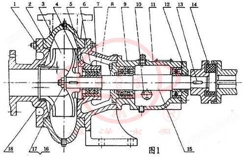
This type of pump mainly consists of: pump cover (1), pump body (2), impeller (3), shaft (15), shaft seal body (4), bearing housing (11), and coupling components (see Figure 1: Structural Diagram)
The pump outlet is vertically upward or can be installed in a horizontal direction. This pump is directly driven by an elastic coupling (belt drive can also be used as needed).
There are only two curved blades inside the impeller, so the flow channel is wide and can accommodate general suspended particles.
There are 4 auxiliary blades on the back of the impeller to balance the axial thrust, and the impeller undergoes static balance testing during manufacturing.
The rotation direction of the pump is clockwise when viewed from the drive end.
The bearings in the bearing box are lubricated with thin oil, and the oil level height is indicated by the oil gauge. The oil level should be at the normal oil level line.
This pump shaft seal adopts oil seal group sealing, with good sealing performance and easy replacement.
The sealing ring is made of cast iron and fixed on the pump cover. It can be replaced with spare parts after wear.
The clearance f between the pump cover and the inlet end of the impeller, the assembly clearance T between the sealing ring and the impeller (as shown in the structural diagram), and the inner diameter of the matched bottom valve are listed in Table 1
Structural schematic diagram
 |
Serial Number |
name |
Serial Number |
name |
1 |
Pump cover |
10 |
oil pointer |
|
2 |
pump body |
11 |
Housing |
|
3 |
impeller |
12 |
Bearing cap |
|
4 |
Shaft seal body |
13 |
flat key |
|
5 |
Shaft seal box |
14 |
elastic ring |
|
6 |
grommet |
15 |
axle |
|
7 |
Shaft sleeve (4PW without) |
16 |
nut |
|
8 |
oil seal |
17 |
grommet |
|
9 |
bearing |
18 |
Sealing ring |
performance parameter
Serial Number |
model |
flow |
lift |
rotational speed |
Power (kW) |
||
m3/h |
L/s |
m |
r/min |
Shaft power |
power |
||
1 |
50PW-65 50PWF-65 |
14.5 |
4 |
16 |
1440 |
2.47 |
4 |
2 |
50PW-65 50PWF-65 |
25 |
6.94 |
32 |
2900 |
3.35 |
4 |
3 |
80PW-100 80PWF-100 |
56 |
15.5 |
13.5 |
1440 |
4.1 |
5.5 |
4 |
80PW-100 80PWF-100 |
90 |
25 |
26 |
2900 |
7 |
11 |
5 |
100PW-125 100PWF-125 |
100 |
27.8 |
12.5 |
1440 |
5.7 |
7.5 |
6 |
21/2PW |
60 |
16.6 |
9.5 |
1440 |
2.5 |
4 |
7 |
21/2PW |
90 |
25 |
26 |
2920 |
11 |
15 |
8 |
21/2PW |
90 |
25 |
43 |
2940 |
17 |
22 |
9 |
4PW |
100 |
27.8 |
11 |
960 |
4.7 |
7.5 |
10 |
4PW |
160 |
44.4 |
25.5 |
1460 |
18 |
30 |
11 |
6PW |
300 |
83.3 |
14 |
980 |
17 |
30 |
12 |
6PW |
350 |
97 |
27 |
1450 |
42 |
55 |
13 |
8PW |
500 |
139 |
13 |
730 |
29 |
45 |
14 |
8PW |
550 |
153 |
25 |
980 |
59.5 |
75 |
15 |
10PW |
800 |
222 |
13.5 |
730 |
40.2 |
75 |
16 |
10PW |
1000 |
278 |
25 |
980 |
92 |
132 |
Assembly and disassembly
First check for any defects that may affect the assembly of each component, then clean them thoroughly before proceeding with the assembly.
1. Prepare paper pads, plugs, and pipe plugs and install them onto the corresponding components.
2. Install the sealing ring, shaft seal box, oil gauge and oil hole cover, and felt stock into the pump cover, bearing body, bearing box, and bearing cover respectively.
3. First, install the bearings into both ends of the shaft, then install them together into the bearing box, and finally install the bearing cover.
4. Install the bearing body, bearing (4PW without) oil seal ring and washer, impeller, washer and impeller nut in sequence and tighten them, then install the pump body and pump cover.
Disassembly and assembly must be done in reverse order.
Installation and precautions
1. Installation
(a)、 Remove the grease and dirt from the base and place it on the foundation.
(b)、 Use a spirit level to check the levelness of the base, and allow for leveling with a wedge iron (for assembled units, the levelness can be checked using the outlet flange plane of the pump).
(c)、 Pour cement into the anchor bolt inspection hole.
(d)、 After the cement dries, check whether the anchor bolts are loose, then tighten the anchor bolts and recheck the levelness.
(e)、 Clean the support plane of the base, the plane of the water pump foot and motor foot, and install the water pump and motor onto the base.
(f)、 A certain gap should be maintained between the couplings, and the centerline of the water pump shaft and motor shaft should be checked for consistency. A thin gasket can be used to adjust them to be concentric. The difference in the outer circumference of the measuring coupling should not exceed 0.1mm, and the gap difference between the end faces of the two couplings should not exceed 0.3mm.
2. Precautions
1) The inlet and outlet water pipes of the pump should be supported, and the pump body should not be used as a support:
2) The outlet water pipeline should be equipped with gate valves;
3) A general trash rack should be installed at the inlet of the pump suction pipeline to prevent larger stones and other objects from being sucked into the pump and damaging the blades.
Start, stop, and operate
1. Start up
1) Check if the bearing box has been filled with oil and if the oil level is within the normal range.
2) Check if the rotation direction of the motor is consistent with the rotation direction of the pump.
3) Close the discharge gate valve and pressure gauge plug, and at the same time, pour water into the suction pipe of the pump through the screw hole on the upper part of the pump body.
4) Start the motor and open the pressure gauge plug.
5) When the water pump reaches normal speed and the pressure gauge displays the corresponding pressure, open the vacuum gauge plug and gradually open the gate valve on the drainage pipeline until needed.
2. Stop it
1) First, slowly close the gate valve of the water outlet pipeline, and then cut off the power supply.
2) In case of freezing season, after stopping the machine, open the square screw plug at the bottom of the pump body and drain the stored water to prevent freezing and cracking.
3) If not used for a long time, each component should be disassembled and cleaned, and rust proof oil should be applied to the sliding surface for proper storage.
3. Operation
1) During the operation of the pump, it is necessary to pay attention to the heating condition of the instruments and bearings, the leakage of the packing, and whether the vibration and noise of the pump are normal. If any abnormalities are found, they should be dealt with in a timely manner.
2) The bearing temperature shall not exceed 75 ℃.
3) The bearing oil should be maintained at the normal oil level line, and should not be too high or too low. If it is too low, it should be refilled in a timely manner.
4) When the clearance between the sealing ring and the impeller exceeds the following specified value, a new sealing ring should be replaced.
When the diameter of the suction port is ≤ 100mm and the total clearance in the diameter direction is ≥ 1.5mm
When the diameter of the suction port is greater than 100mm and the total distance in the diameter direction is ≥ 2mm
Fault analysis and troubleshooting methods
Fault phenomenon |
Possible causes |
Troubleshooting |
||||||||||
Insufficient flow or no water output |
|
|
||||||||||
Unable to start |
|
|
||||||||||
Stator burnt out |
|
|
||||||||||
Excessive current |
|
|
Online inquiry
-
Contacts
-
Company
-
Telephone
-
Email
-
WeChat
-
Verification Code
-
Message Content
-