
VIP member
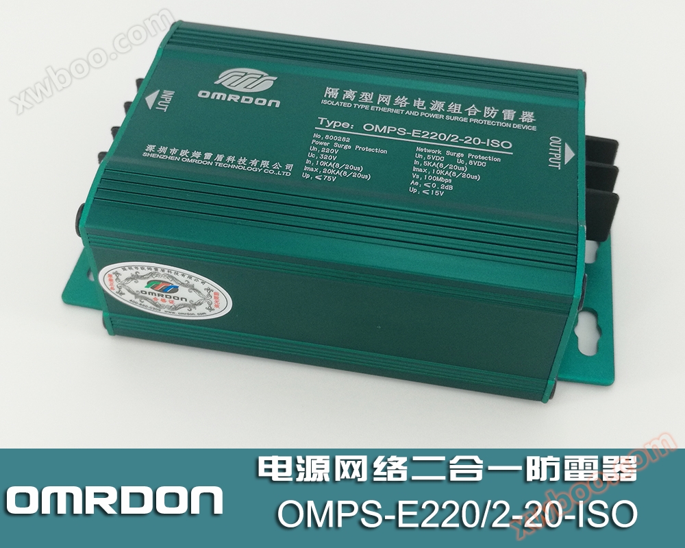
OMPS-E220/2-20-ISO isolated network power supply 2-in-1 lightning arrester (2-in-1 surge protector)
Product specifications: Installation and usage scenario: Terminal equipment lightning arrester category: Power+signal nominal working voltage (Un): 22
Product details
Product Introduction
Ohm Thunder Shield(OMRDON) OMPS-E220/2-20-ISO, OMPS-E24/2-20-ISO, OMPS-E12/2-20-ISO isolated network power combination surge protector (also known as power network two in one lightning arrester, power network two in one lightning arrester, power network two in one surge protector) is designed according to IEC and GB standards, mainly used for lightning electromagnetic pulse (LEMP) protection of various weak current equipment, security equipment, telecommunications equipment, network equipment power supplies and 100Mbps network signal lines. It is an integrated multifunctional surge protector.
Features
1. Maximum current capacity: 10KA or 20KA (8/20 μ S), the power supply line adopts a two-stage composite balanced safest line, differential mode (line to line), common mode (line to ground) full mode protection, residual voltage, especially suitable for outdoor equipment with high lightning energy and strict requirements for residual voltage values.
2. The internal network circuit also adopts a two-stage series composite protection, differential mode (line to line), common mode (line to ground) full mode protection, residual low voltage, and long service life;
3. Network protection has isolation function, isolating signal interference and enhancing signal transmission rate
4. Can effectively prevent equipment damage caused by instantaneous increase in potential difference between power supply, network and other lines;
5. Adopting an integrated structure and minimizing volume while meeting relevant parameters, without taking up space;
6. Power surge protection port with LED failure indicator (green: normal; off: failure);
Installation method of lightning arrester
1. This surge protector is installed in series in front of the protected equipment port (with the "INPUT" marked end connected to the line and the "OUTPUT" marked end connected to the protected equipment), and is grounded to the lightning protection grid or equipotential terminal copper bar.
2. Line terminal connection method (power supply part): Connect "L/+" and "N/-" at both ends of the power supply respectively.
3. RJ45 network signal line connection method: serial installation, RJ45 crystal head can be directly plugged in.
4. The cross-section of the grounding wire should be ≥ 2.5mm2And as short as possible. The installation of this lightning protection product requires a grounding resistance of less than4 Ω, the lightning protection performance is optimal when the grounding wire and grounding resistance are qualified.
5. This lightning arrester is maintenance free, and its working condition should be checked and recorded in a timely manner after thunderstorms.
Precautions for installation of lightning arrester
1. All ports of the lightning arrester output end are connected to the protected equipment.
2. Do not connect the positive and negative lines in reverse or incorrectly, and remember not to carry out live work.
3. The closer the lightning arrester is installed at the front end of the protected equipment, the better the effect.
4. The equipment needs to be regularly inspected and replaced immediately after product degradation.
5. The grounding must be good and the grounding resistance should not exceed 4 Ω. For some difficult to ground areas such as mountainous areas/sandy environments, the grounding resistance can be relaxed to 10 Ω.
|
name |
Isolation type network power combination surge protector |
|||||
|
SPD category |
Composite SPD |
|||||
|
SPD function |
Equipped with voltage limiting, current limiting, and isolation functions |
|||||
|
model |
OMPS-E12/2- ISO OMPS-E12/2-20- ISO |
OMPS- E24/2-ISO OMPS- E24/2-20-ISO |
OMPS- E24/2-ISO OMPS- E24/2-20-ISO |
|||
|
type |
power supply |
network |
power supply |
network |
power supply |
network |
|
Nominal operating voltage Un |
12V |
5V |
24V |
5V |
220V |
5V |
|
Maximum continuous operating voltage Uc |
18V |
8V |
36V |
8V |
320V |
8V |
|
Nominal load current IL |
5A |
500mA |
5A |
500mA |
5A |
500mA |
|
Nominal discharge current (8/20 μ s) In |
5KA/10KA |
5KA |
5KA/10KA |
5KA |
5KA/10KA |
5KA |
|
Maximum discharge current (8/20 μ s) Imax |
10KA/20KA |
10KA |
10KA/20KA |
10KA |
10KA/20KA |
10KA |
|
Voltage protection level Up |
≤36V |
≤20V |
≤75V |
≤20V |
≤700V |
≤20V |
|
Response time Ta |
≤25ns |
≤1ns |
≤25ns |
≤1ns |
≤25ns |
≤1ns |
|
Transmission rate Vs |
- |
100Mbps |
- |
100Mbps |
- |
100Mbps |
|
Insertion loss Ae |
- |
≤0.3db |
- |
≤0.3db |
- |
≤0.3db |
|
interface type |
terminal block |
RJ45/1236 |
terminal block |
RJ45/1236 |
terminal block |
RJ45/1236 |
|
Installation wiring specifications |
2.5mm2 |
- |
2.5mm2 |
- |
2.5mm2 |
- |
|
Failure Indication |
Green: Normal |
-- |
Green: Normal |
-- |
Green: Normal |
-- |
|
overstressed fault mode |
The voltage limiting part of SPD has an internal open circuit on the network side, and the circuit is not running, but the equipment is still protected by the open circuit. |
|||||
|
temperature range |
- 40℃…+ 85℃ |
|||||
|
Installation method |
Wall fixing or horizontal fixing (placement) |
|||||
|
Overall dimensions |
106x58x35mm |
|||||
|
housing material |
aluminum alloy |
|||||
|
Shell protection level |
IP20 |
|||||
|
Test Standard |
GB/T18802.1-2011,GB/T18802. 21-2016 |
|||||

|
packagingbox:CTN. |
carton packaging |
|
Quantity: QTY |
1 PCS |
|
Size: DIM |
L115*W38*H72mm |
|
Weight (gross): G.W |
300g |
|
Weight (net): N.W |
330g |
Online inquiry
-
Contacts
-
Company
-
Telephone
-
Email
-
WeChat
-
Verification Code
-
Message Content
-