
VIP member

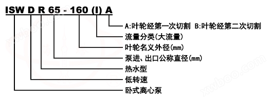
ISWD horizontal single-stage low-speed pipeline clean water pump
ISW, ISWR, and ISWR horizontal single-stage single suction low-speed pipeline clean water pumps are optimized and designed based on the performance pa
Product details
Model meaning
Product Introduction
ISWD, ISWDR, and ISWDR horizontal single-stage single suction low-speed pipeline clean water pumps are designed based on the performance parameters of IS and IR centrifugal pumps, referring to the ISO2858 standard, using a hydraulic model. It is an ideal new generation energy-saving horizontal pump product.
Product Features
1. Smooth operation: The absolute concentricity of the pump shaft and excellent dynamic and static balance of the impeller ensure smooth operation without any vibration.
2. Drip proof: Hard alloy seals made of different materials ensure that there is no leakage during the transportation of different media.
3. Low noise: The water pump under two low-noise bearings runs smoothly, with almost no noise except for weak motor noise.
4. Low failure rate: The structure is simple and reasonable, and high-quality matching is used for key parts, greatly improving the fault free working time of the whole machine.
5. Easy to maintain: replace mechanical seals and bearings, simple and convenient.
6. More land saving: The exit can be arranged in three directions: left, right, and up, which is convenient for pipeline layout and installation, saving space.
7. ISW horizontal pipeline centrifugal pump is used for conveying clean water and other liquids with physical and chemical properties similar to clean water. It is suitable for industrial and urban water supply, high-rise building pressurized water supply, garden sprinkler irrigation, fire protection pressurization, long-distance transportation, HVAC refrigeration cycle, bathroom and other cold and warm water circulation pressurization and equipment matching. The operating temperature T ≤ 80 ℃.
8. The ISWR horizontal hot water pipeline centrifugal pump is widely used in metallurgy, chemical industry, textile, papermaking, as well as hotels, restaurants, and other boiler hot water pressurized circulation transportation and urban heating systems. The ISWR type uses a temperature T ≤ 120 ℃.
9. ISWH horizontal chemical pump is used for conveying liquids that do not contain solid particles, are corrosive, and have a viscosity similar to water. It is suitable for industries such as petroleum, chemical, metallurgical, power, papermaking, food and pharmaceuticals, and synthetic fibers. The operating temperature ranges from -20 ℃ to+120 ℃.
10. ISWB horizontal pipeline oil pump is used to transport oil products such as gasoline, kerosene, diesel, or flammable and late explosive liquids. The temperature of the transported medium is -20 ℃ to+120 ℃.
Product Usage
Terms of Use Scope of Application structural diagram
1. The ISW pump is suitable for industrial and urban water supply and drainage, high-rise building pressurized water supply, garden sprinkler irrigation, fire boosting, long-distance water supply, HVAC refrigeration cycle, bathroom warm water cycle boosting, as well as supporting various water supply equipment and boilers. Used for conveying clean water or other liquids with physical or chemical properties similar to clean water, with a usage temperature not exceeding 85 degrees Celsius℃。
2. The ISWR pump is suitable for metallurgy, chemical industry, textile, wood processing, papermaking, as well as restaurants, bathrooms, hotels, boiler hot water boosting circulation, and urban housing heating circulation, with a usage temperature not exceeding 120 ℃.
3. The ISWD pump is suitable for situations where low environmental noise is required, and the operating temperature should not exceed 100 ℃.
1. The suction pressure is ≤ 1.0Mpa, or the working pressure of the pump system is ≤ 1.6Mpa, that is, the pump suction inlet pressure+pump head is ≤ 1.6Mpa, and the pump static pressure test pressure is 2.5Mpa. Please specify the system working pressure when ordering. When the working pressure of the pump system is greater than 1.6Mpa, it should be separately stated when ordering, so that the overcurrent components and connecting parts of the pump can be made of cast steel materials during manufacturing.
2. Environmental temperature<40 ℃, relative humidity<95%.
3. The volume content of solid particles in the conveyed medium shall not exceed 0.1% of the unit volume, and the particle size shall be less than 0.2mm
Note: If the medium used is with small particles, please specify when ordering so that wear-resistant mechanical seals can be used.
1. The high working pressure of the system is 1.6MPa, which means that the pump suction pressure+pump head is ≤ 1.6MPa (if the working pressure of the pump system is greater than 1.6MPa, it should be separately specified when ordering, so that cast steel can be used in the manufacturing of the pump's overcurrent components and connecting components)
2. The conveying medium is clear water or other liquids with physical and chemical properties similar to clear water.
3. Environmental temperature ≤ 40 ℃, altitude ≤ 1000m, relative humidity ≤ 95%.
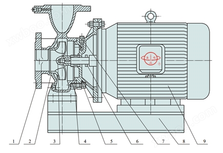 serial numbernameserial numbername
1pump body6Water blocking ring
2impeller7screw plug
3impeller nut8base
4mechanical seal9motor
5pump cover
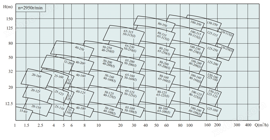
Spectrogram
 |
performance parameters
model |
caliber |
traffic |
head |
efficiency |
speed |
Motor power |
Required cavitation allowance |
weight |
|
mm |
m3/h |
L/S |
m |
% |
r/min |
KW |
(NPSH)r |
Kg |
|
40-200 |
40 |
2.2 3.2 4.2 |
0.61 0.89 1.17 |
13 12.5 12 |
31 |
1450 |
0.75 |
2.5 |
38 |
40-250 |
40 |
2.2 3.2 4.2 |
0.61 0.89 1.17 |
20.5 20 18.5 |
25 |
1450 |
1.1 |
2.5 |
52 |
40-250A |
40 |
2.0 2.8 3.7 |
0.56 0.78 1.03 |
16.4 16 15 |
25 |
1450 |
0.75 |
2.5 |
47 |
40-250B |
40 |
1.6 2.3 3.4 |
0.44 0.64 0.94 |
13.2 13 12 |
24 |
1450 |
0.75 |
2.5 |
46 |
40-160(I) |
40 |
3.8 6.3 7.5 |
1.06 1.75 2.08 |
8.5 8.0 7.5 |
47 |
1450 |
0.75 |
2.5 |
43 |
40-200(I) |
40 |
3.8 6.3 7.5 |
1.06 1.75 2.08 |
13.1 12.5 12 |
40 |
1450 |
0.75 |
2.5 |
45 |
40-200(I)A |
40 |
3.3 5.5 6.5 |
0.92 1.53 1.81 |
10 9.5 9 |
39 |
1450 |
0.75 |
2.5 |
44 |
40-250(I) |
40 |
3.8 6.3 7.5 |
1.06 1.75 2.08 |
20.5 20 19.5 |
32 |
1450 |
1.5 |
2.5 |
54 |
40-250(I)A |
40 |
3.4 5.6 6.7 |
0.94 1.56 1.86 |
16.4 16 15.6 |
32 |
1450 |
1.1 |
2.5 |
49 |
40-250(I)B |
40 |
3.1 5.1 6.1 |
0.86 1.42 1.69 |
13.2 13 12.5 |
30 |
1450 |
0.75 |
2.5 |
42 |
model
|
caliber |
traffic |
head |
efficiency |
speed |
Motor power |
Required cavitation allowance |
weight |
|
mm |
m3/h |
L/S |
m |
% |
r/min |
KW |
(NPSH)r |
Kg |
|
50-160 |
50 |
3.8 6.3 7.5 |
1.06 1.75 2.08 |
8.5 8.0 7.5 |
47 |
1450 |
0.75 |
2.5 |
42 |
50-200 |
50 |
3.8 6.3 7.5 |
1.06 1.75 2.08 |
13.1 12.5 12 |
40 |
1450 |
0.75 |
2.5 |
48 |
50-200A |
50 |
3.3 5.5 6.5 |
0.92 1.53 1.81 |
10 9.5 9 |
39 |
1450 |
0.55 |
2.5 |
46 |
50-250 |
50 |
3.8 6.3 7.5 |
1.06 1.75 2.08 |
20.5 20 19.5 |
32 |
1450 |
1.5 |
2.5 |
58 |
50-250A |
50 |
3.4 5.6 6.7 |
0.94 1.56 1.86 |
16.4 16 15.6 |
32 |
1450 |
1.1 |
2.5 |
50 |
50-250B |
50 |
3.1 5.1 6.1 |
0.86 1.42 1.69 |
13.2 13 12.5 |
30 |
1450 |
0.75 |
2.5 |
49 |
50-160(I) |
50 |
7.5 12.5 15 |
2.08 3.47 4.17 |
8.8 8 7.2 |
59 |
1450 |
0.75 |
2.8 |
46 |
50-200(I) |
50 |
7.5 12.5 15 |
2.08 3.47 4.17 |
13.2 12.5 11.8 |
54 |
1450 |
1.1 |
2.8 |
52 |
50-200(I)A |
50 |
6.8 11.3 13.5 |
1.89 3.14 3.75 |
10.7 10.1 9.6 |
53 |
1450 |
0.75 |
2.8 |
48 |
50-250(I) |
50 |
7.5 12.5 15 |
2.08 3.47 4.17 |
21 20 19.4 |
45 |
1450 |
2.2 |
2.8 |
73 |
50-250(I)A |
50 |
7.0 11.7 14.1 |
1.94 3.25 3.92 |
18.4 17.6 17 |
44 |
1450 |
1.5 |
2.8 |
65 |
50-250(I)B |
50 |
6.1 10.2 12.3 |
1.69 2.83 3.42 |
14.1 13.4 13.0 |
43 |
1450 |
1.1 |
2.8 |
60 |
50-315(I) |
50 |
7.5 12.5 15 |
2.08 3.47 4.17 |
32.3 32 31.7 |
36 |
1450 |
4 |
2.8 |
89 |
50-315(I)A |
50 |
7 11.7 14 |
1.94 3.25 3.92 |
28.1 28 27.6 |
36 |
1450 |
3 |
2.8 |
84 |
50-315(I)B |
50 |
6.1 10.2 12.1 |
1.69 2.81 3.36 |
21.2 21 20.8 |
34 |
1450 |
3 |
2.8 |
82 |
model
|
caliber |
traffic |
head |
efficiency |
speed |
Motor power |
Required cavitation allowance |
weight |
|
mm |
m3/h |
L/S |
m |
% |
r/min |
KW |
(NPSH)r |
Kg |
|
65-160 |
65 |
7.5 12.5 15 |
2.08 3.47 4.17 |
8.8 8 7.2 |
59 |
1450 |
0.55 |
2.8 |
46 |
65-200 |
65 |
7.5 12.5 15 |
2.08 3.47 3.75 |
13.2 12.5 11.8 |
54 |
1450 |
1.1 |
2.8 |
52 |
65-200A |
65 |
6.8 11.3 13.5 |
1.89 3.14 3.75 |
10.7 10.1 9.6 |
53 |
1450 |
0.75 |
2.8 |
48 |
65-250 |
65 |
7.5 12.5 15 |
2.08 3.47 4.17 |
21 20 19.4 |
45 |
1450 |
2.2 |
2.8 |
76 |
65-250A |
65 |
7.0 11.7 14.1 |
1.94 3.25 3.92 |
18.4 17.6 17 |
44 |
1450 |
1.5 |
2.8 |
68 |
65-250B |
65 |
6.1 10.2 12.3 |
1.69 2.83 3.42 |
14.1 13.4 13.0 |
43 |
1450 |
1.1 |
2.8 |
63 |
65-315 |
65 |
7.5 12.5 15 |
2.08 3.47 4.17 |
32.3 32 31.7 |
36 |
1450 |
4 |
2.8 |
89 |
65-315A |
65 |
7 11.7 14 |
1.94 3.25 3.92 |
28.1 28 27.6 |
36 |
1450 |
3 |
2.8 |
85 |
65-315B |
65 |
6.1 10.1 12.1 |
1.69 2.81 3.36 |
21.2 21 20.8 |
34 |
1450 |
3 |
2.8 |
82 |
model |
caliber |
traffic |
head |
efficiency |
speed |
Motor power |
Required cavitation allowance |
weight |
|
mm |
m3/h |
L/S |
m |
% |
r/min |
KW |
(NPSH)r |
Kg |
|
65-125(I) |
65 |
15 25 30 |
4.17 6.94 8.33 |
5.6 5 4.5 |
70 |
1450 |
0.75 |
2.8 |
49 |
65-125(I)A |
65 |
13.1 21.8 26.1 |
3.05 6.05 7.25 |
4.3 3.8 3.4 |
65 |
1450 |
0.75 |
2.8 |
48 |
65-160(I) |
65 |
15 25 30 |
4.17 6.94 8.33 |
9 8 7.2 |
68 |
1450 |
1.1 |
2.8 |
54 |
65-160(I)A |
65 |
13.0 21.6 25.9 |
3.61 6.0 7.19 |
6.7 6.0 5.4 |
65 |
1450 |
0.75 |
2.8 |
48 |
65-200(I) |
65 |
15 25 30 |
4.17 6.94 8.33 |
13.2 12.5 11.8 |
64 |
1450 |
2.2 |
2.8 |
71 |
65-200(I)A |
65 |
14.0 23.3 27.9 |
3.89 6.47 7.75 |
11.5 10.9 10.2 |
63 |
1450 |
1.5 |
2.8 |
62 |
65-250(I) |
65 |
15 25 30 |
4.17 6.94 8.33 |
21 20 18.8 |
59 |
1450 |
3 |
2.8 |
85 |
65-250(I)A |
65 |
13.3 22.2 26.6 |
3.69 6.17 7.39 |
16.6 15.8 14.8 |
58 |
1450 |
2.2 |
2.8 |
80 |
65-250(I)B |
65 |
11.9 19.8 23.8 |
3.31 5.5 6.61 |
13.2 12.6 11.8 |
57 |
1450 |
1.5 |
2.8 |
74 |
65-315(I) |
65 |
15 25 30 |
4.17 6.94 8.33 |
32.5 32 31.5 |
50 |
1450 |
5.5 |
2.8 |
120 |
65-315(I)A |
65 |
14 23 28 |
3.89 6.39 7.78 |
28.3 27.9 27.4 |
50 |
1450 |
4 |
2.8 |
110 |
65-315(I)B |
65 |
12.1 20.2 24.2 |
3.36 5.61 6.75 |
21.3 21 30.6 |
49 |
1450 |
3 |
2.8 |
100 |
model
|
caliber |
traffic |
head |
efficiency |
speed |
Motor power |
Required cavitation allowance |
weight |
|
mm |
m3/h |
L/S |
m |
% |
r/min |
KW |
(NPSH)r |
Kg |
|
80-125 |
80 |
15 25 30 |
4.17 6.94 8.33 |
5.6 5 4.5 |
70 |
1450 |
0.75 |
2.8 |
48 |
80-125A |
80 |
13.1 21.8 26.1 |
3.05 6.05 7.25 |
4.3 3.8 3.4 |
65 |
1450 |
0.75 |
2.8 |
45 |
80-160 |
80 |
15 25 30 |
4.17 6.94 8.33 |
9 8 7.2 |
68 |
1450 |
1.1 |
2.8 |
55 |
80-160A |
80 |
13.0 21.6 25.9 |
3.61 6.0 7.19 |
6.7 6.0 5.4 |
65 |
1450 |
0.75 |
2.8 |
51 |
80-200 |
80 |
15 25 30 |
4.17 6.94 8.33 |
13.2 12.5 11.8 |
64 |
1450 |
2.2 |
2.8 |
72 |
80-200A |
80 |
14.0 23.3 27.9 |
3.89 6.47 7.75 |
11.5 10.9 10.2 |
63 |
1450 |
1.5 |
2.8 |
64 |
80-250 |
80 |
15 25 30 |
4.17 6.94 8.33 |
21 20 18.8 |
59 |
1450 |
3 |
2.8 |
89 |
80-250A |
80 |
13.3 22.2 26.6 |
3.69 6.17 7.39 |
16.6 15.8 14.8 |
58 |
1450 |
2.2 |
2.8 |
85 |
80-250B |
80 |
11.9 19.8 23.8 |
3.31 5.5 6.61 |
13.2 12.6 11.8 |
57 |
1450 |
1.5 |
2.8 |
78 |
80-315 |
80 |
15 25 30 |
4.17 6.94 8.33 |
32.5 32 31.5 |
50 |
1450 |
5.5 |
2.8 |
130 |
80-315A |
80 |
14 23 28 |
3.89 6.39 7.78 |
28.3 27.9 27.4 |
50 |
1450 |
4.0 |
2.8 |
102 |
80-315B |
80 |
12.1 20.2 24.3 |
3.36 5.61 6.75 |
21.3 21 20.6 |
49 |
1450 |
3 |
2.8 |
95 |
model |
caliber |
traffic |
head |
efficiency |
speed |
Motor power |
Required cavitation allowance |
weight |
|
mm |
m3/h |
L/S |
m |
% |
r/min |
KW |
(NPSH)r |
Kg |
|
80-100(I) |
80 |
30 50 60 |
8.33 13.89 16.67 |
3.5 3 2.5 |
73 |
1450 |
0.75 |
3.0 |
58 |
80-125(I) |
80 |
30 50 60 |
8.33 13.89 16.67 |
6 5 4 |
73 |
1450 |
1.1 |
3.0 |
61 |
80-125(I)A |
80 |
26.8 44.6 53.5 |
7.44 12.4 14.9 |
4.8 4 3.2 |
63 |
1450 |
2.2 |
3.0 |
61 |
80-160(I) |
80 |
30 50 60 |
8.33 13.89 16.67 |
9.2 8 6.8 |
73 |
1450 |
2.2 |
3.0 |
82 |
80-160(I)A |
80 |
26.7 44.5 53.4 |
7.42 12.36 14.83 |
7.3 6.3 5.4 |
71 |
1450 |
1.5 |
3.0 |
74 |
80-200(I) |
80 |
30 50 60 |
8.33 13.89 16.67 |
13.5 12.5 11.8 |
72 |
1450 |
3.0 |
3.0 |
97 |
80-200(I)A |
80 |
26.7 44.6 53.5 |
7.42 12.36 14.83 |
10.7 9.9 9.4 |
71 |
1450 |
2.2 |
3.0 |
93 |
80-250(I) |
80 |
30 50 60 |
8.33 13.89 16.67 |
21.3 20 19 |
66 |
1450 |
5.5 |
3.0 |
134 |
80-250(I)A |
80 |
28 46.7 56 |
7.78 12.97 15.56 |
18.6 17.4 16.6 |
65 |
1450 |
4.0 |
3.0 |
106 |
80-250(I)B |
80 |
24.2 40.4 48.5 |
6.72 11.22 13.47 |
13.9 13.1 12.4 |
63 |
1450 |
3.0 |
3.0 |
100 |
80-315(I) |
80 |
30 50 60 |
8.33 13.89 16.67 |
34 32 30 |
61 |
1450 |
11.0 |
3.0 |
217 |
80-315(I)A |
80 |
28 46.7 56 |
7.78 12.97 15.56 |
29.6 27.9 26.1 |
61 |
1450 |
7.5 |
3.0 |
180 |
80-315(I)B |
80 |
24.3 40.5 48.6 |
6.72 11.22 13.47 |
22.3 21 19.1 |
60 |
1450 |
5.5 |
3.0 |
166 |
model
|
caliber |
traffic |
head |
efficiency |
speed |
Motor power |
Required cavitation allowance |
weight |
|
mm |
m3/h |
L/S |
m |
% |
r/min |
KW |
(NPSH)r |
Kg |
|
100-100 |
100 |
30 50 60 |
8.33 13.89 16.67 |
3.5 3 2.5 |
73 |
1450 |
0.75 |
3.0 |
62 |
100-125 |
100 |
30 50 60 |
8.33 13.89 16.67 |
6 5 4 |
73 |
1450 |
1.1 |
3.0 |
70 |
100-125A |
100 |
26.8 44.6 53.5 |
7.44 12.4 14.9 |
4.8 4 3.2 |
63 |
1450 |
1.1 |
3.0 |
68 |
100-160 |
100 |
30 50 60 |
8.33 13.89 16.67 |
9.2 8 6.8 |
73 |
1450 |
2.2 |
3.0 |
87 |
100-160A |
100 |
26.7 44.5 53.4 |
7.42 12.36 14.83 |
7.3 6.3 5.4 |
71 |
1450 |
1.5 |
3.0 |
79 |
100-200 |
100 |
30 50 60 |
8.33 13.89 16.67 |
13.5 12.5 11.8 |
72 |
1450 |
3.0 |
3.0 |
100 |
100-200A |
100 |
26.7 44.6 53.5 |
7.42 12.36 14.83 |
10.7 9.9 9.4 |
71 |
1450 |
2.2 |
3.0 |
90 |
100-250 |
100 |
30 50 60 |
8.33 13.89 16.67 |
21.3 20 19 |
66 |
1450 |
5.5 |
3.0 |
140 |
100-250A |
100 |
28 46.7 56 |
7.78 12.97 15.56 |
18.6 17.6 16.6 |
65 |
1450 |
4.0 |
3.0 |
112 |
100-250B |
100 |
24.2 40.4 48.5 |
6.72 11.22 13.47 |
13.9 13.1 12.4 |
63 |
1450 |
3.0 |
3.0 |
105 |
100-315 |
100 |
30 50 60 |
8.33 13.89 16.67 |
34 32 30 |
61 |
1450 |
11.0 |
3.0 |
225 |
100-315A |
100 |
28 46.7 56 |
7.78 12.97 15.56 |
29.6 27.9 26.1 |
61 |
1450 |
7.5 |
3.0 |
180 |
100-315B |
100 |
24.3 40.5 48.6 |
6.72 11.22 13.47 |
22.3 21 19.1 |
60 |
1450 |
5.5 |
3.0 |
165 |
model |
caliber |
traffic |
head |
efficiency |
speed |
Motor power |
Required cavitation allowance |
weight |
|
mm |
m3/h |
L/S |
m |
% |
r/min |
KW |
(NPSH)r |
Kg |
|
100-125(I) |
100 |
60 100 120 |
16.67 27.78 33.33 |
6.5 5 4 |
78 |
1450 |
2.2 |
3.0 |
95 |
100-125(I)A |
100 |
52.2 87.1 104 |
14.5 24.2 28.9 |
4.3 3.8 3.4 |
76 |
1450 |
1.5 |
3.0 |
87 |
100-160(I) |
100 |
60 100 120 |
16.7 27.78 33.33 |
10 8 7 |
78 |
1450 |
4.0 |
3.0 |
118 |
100-160(I)A |
100 |
52.2 87.1 104 |
14.5 24.2 28.9 |
7.3 6.3 5.4 |
76 |
1450 |
3.0 |
3.0 |
113 |
100-200(I) |
100 |
60 100 120 |
16.67 27.78 33.33 |
14.0 12.5 11 |
75 |
1450 |
5.5 |
3.0 |
148 |
100-200(I)A |
100 |
51.7 86.1 103 |
14.36 23.92 28.61 |
10.8 9.3 8.2 |
73 |
1450 |
4.0 |
3.0 |
123 |
100-250(I) |
100 |
60 100 120 |
16.67 22.78 33.33 |
21.5 20 18.5 |
74 |
1450 |
11.0 |
3.0 |
208 |
100-250(I)A |
100 |
56 93.3 112 |
15.56 25.92 31.11 |
18.7 17.4 16.1 |
73 |
1450 |
7.5 |
3.0 |
165 |
100-250(I)B |
100 |
52.2 87 104 |
14.5 24.17 28.89 |
16 15 14 |
72 |
1450 |
5.5 |
3.0 |
149 |
100-315(I) |
100 |
60 100 120 |
16.67 22.78 33.33 |
33.5 32 30.5 |
71 |
1450 |
15.0 |
3.0 |
234 |
100-315(I)A |
100 |
55.0 91.0 110.0 |
15.28 25.28 30.56 |
28 27 25.7 |
71 |
1450 |
11.0 |
3.0 |
213 |
100-315(I)B |
100 |
47 79.0 95 |
13.06 21.94 26.39 |
21 20 19 |
70 |
1450 |
7.5 |
3.0 |
165 |
100-400(I) |
100 |
60 100 120 |
16.67 22.78 33.33 |
52 50 48.5 |
65 |
1450 |
30.0 |
3.0 |
375 |
100-400(I)A |
100 |
56.4 94 113 |
15.67 26.11 31.39 |
46 44 43 |
65 |
1450 |
22.0 |
3.0 |
295 |
100-400(I)B |
100 |
52.3 87 105 |
14.53 24.17 29.17 |
39 38 37 |
64 |
1450 |
18.5 |
3.0 |
257 |
100-400(I)C |
100 |
48.6 81 97 |
13.54 22.56 26.94 |
34 32.8 32 |
62 |
1450 |
15.0 |
3.0 |
239 |
model
|
caliber |
traffic |
head |
efficiency |
speed |
Motor power |
Required cavitation allowance |
weight |
|
mm |
m3/h |
L/S |
m |
% |
r/min |
KW |
(NPSH)r |
Kg |
|
125-125 |
125 |
48 80 96 |
13.3 22.2 26.7 |
5.5 5 4.3 |
76 |
1450 |
2.2 |
3.0 |
148 |
125-125A |
125 |
43 71.5 66 |
11.6 19.9 13.9 |
4.4 4 3.4 |
75 |
1450 |
1.5 |
3.0 |
125 |
125-160 |
125 |
48 80 96 |
13.3 22.2 26.7 |
9 8 7 |
74 |
1450 |
3.0 |
3.0 |
205 |
125-160A |
125 |
42 69.3 83 |
11.9 19.3 23 |
6.8 6 5.3 |
73 |
1450 |
2.2 |
3.0 |
165 |
125-200 |
125 |
48 80 96 |
13.3 23.2 26.7 |
13.8 12.5 11.5 |
73 |
1450 |
5.5 |
3.0 |
249 |
125-200A |
125 |
45 75 90 |
12.5 20.8 25 |
12 11 10 |
72 |
1450 |
4.0 |
3.0 |
237 |
125-250 |
125 |
48 80 96 |
13.3 22.2 26.7 |
22 20 18.3 |
72 |
1450 |
7.5 |
2.8 |
220 |
125-250A |
125 |
45 75 90 |
12.5 20.8 25 |
19 17.5 16 |
71 |
1450 |
7.5 |
2.8 |
210 |
125-250B |
125 |
41.5 69 83 |
11.5 11.2 23 |
16.3 15 13.8 |
70 |
1450 |
5.5 |
2.8 |
195 |
125-315 |
125 |
48 80 96 |
13.3 22.2 26.7 |
33.3 32 29.8 |
67 |
1450 |
15.0 |
2.5 |
300 |
125-315A |
125 |
45 75 90 |
12.5 20.8 25 |
29.3 27.5 26 |
66 |
1450 |
11.0 |
2.5 |
282 |
125-315B |
125 |
43 72 96 |
11.9 20 23.9 |
26.5 25 23.8 |
65 |
1450 |
11.0 |
2.5 |
282 |
model |
caliber |
traffic |
head |
efficiency |
speed |
Motor power |
Required cavitation allowance |
weight |
|
mm |
m3/h |
L/S |
m |
% |
r/min |
KW |
(NPSH)r |
Kg |
|
150-200 |
150 |
96 160 192 |
26.7 44.4 53.3 |
13.8 12.5 11.5 |
77 |
1450 |
11 |
5.5 |
305 |
150-200A |
150 |
90 150 180 |
25 41.7 50 |
12 11 10 |
76 |
1450 |
7.5 |
5.5 |
276 |
150-250 |
150 |
96 160 192 |
26.7 44.4 53.3 |
22 20 18.3 |
75 |
1450 |
15 |
5.0 |
310 |
150-250A |
150 |
90 150 180 |
25 41.7 50 |
19 17.5 16 |
74 |
1450 |
11 |
5.5 |
303 |
150-250B |
150 |
84 140 168 |
23.3 39 46.7 |
16.3 15 13.8 |
73 |
1450 |
7.5 |
5.5 |
281 |
150-315 |
150 |
96 160 192 |
26.7 44.4 53.3 |
33.3 32 29.8 |
70 78 73 |
1450 |
30 |
2.5 |
410 |
150-315A |
150 |
90 150 180 |
25 41.7 50 |
29.3 27.5 26 |
69 77 77 |
1450 |
22 |
3.5 |
335 |
150-315B |
150 |
84 140 168 |
23.3 39 46.7 |
25 24 21 |
76 |
1450 |
18.5 |
3.5 |
315 |
150-400 |
150 |
96 160 192 |
26.7 44.4 53.3 |
53 50 44 |
68 75 71 |
1450 |
45 |
3.5 |
490 |
150-400A |
150 |
90 150 180 |
25 41.7 50 |
46.6 44 38.3 |
67 74 70 |
1450 |
37 |
3.5 |
454 |
150-400B |
150 |
84 140 168 |
23.3 39 46.7 |
40 38 33 |
73 |
1450 |
30 |
3.5 |
435 |
model |
caliber |
traffic |
head |
efficiency |
speed |
Motor power |
Required cavitation allowance |
weight |
|
mm |
m3/h |
L/S |
m |
% |
r/min |
KW |
(NPSH)r |
Kg |
|
150-200(I) |
150 |
120 200 240 |
33.3 55.6 66.7 |
13.8 12.5 11.5 |
65 76 74 |
1450 |
15 |
4.5 |
310 |
150-200(I)A |
150 |
112 187 224 |
31.1 51.9 62.2 |
12 11 10 |
64 75 73 |
1450 |
11 |
4.5 |
303 |
150-250(I) |
150 |
140 200 260 |
38.9 55.6 72.2 |
22 20 18.3 |
75 |
1450 |
18.5 |
5.0 |
340 |
150-250(I)A |
150 |
131 187 243 |
36.4 51.9 67.5 |
19 17.5 16 |
74 |
1450 |
15 |
5.5 |
325 |
150-250(I)B |
150 |
121 173 225 |
33.5 48.1 62.5 |
16.3 15 13.8 |
73 |
1450 |
11 |
5.5 |
300 |
150-315(I) |
150 |
140 200 260 |
38.9 55.6 72.2 |
33.3 32 29.8 |
70 78 73 |
1450 |
30 |
2.5 |
410 |
150-315(I)A |
150 |
131 187 243 |
36.4 51.9 67.5 |
29.3 27.5 26 |
69 77 77 |
1450 |
22 |
3.5 |
335 |
150-315(I)B |
150 |
121 173 225 |
33.5 48.1 62.5 |
25 24 21 |
76 |
1450 |
18.5 |
3.5 |
315 |
150-400(I) |
150 |
140 200 260 |
38.9 55.6 72.2 |
53 50 44 |
68 75 71 |
1450 |
45 |
3.5 |
490 |
150-400(I)A |
150 |
131 187 243 |
36.4 51.9 67.5 |
46.6 44 38.3 |
67 74 70 |
1450 |
37 |
3.5 |
454 |
150-400(I)B |
150 |
121 173 225 |
33.5 48.1 62.5 |
40 38 33 |
73 |
1450 |
30 |
3.5 |
435 |
150-500(I) |
150 |
140 200 260 |
38.9 55.6 72.2 |
87 80 73 |
73 |
1450 |
90 |
3.5 |
1215 |
150-500(I)A |
150 |
131 187 243 |
36.4 51.9 67.5 |
76 70 84 |
73 |
1450 |
75 |
3.5 |
1108 |
150-500(I)B |
150 |
121 173 225 |
33.5 48.1 62.5 |
65 60 55 |
73 |
1450 |
55 |
3.5 |
920 |
model |
caliber |
traffic |
head |
efficiency |
speed |
Motor power |
Required cavitation allowance |
weight |
|
mm |
m3/h |
L/S |
m |
% |
r/min |
KW |
(NPSH)r |
Kg |
|
200-200 |
200 |
140 200 260 |
38.9 55.6 72.2 |
13.8 12.5 10.6 |
68 78 78 |
1450 |
15 |
3.0 |
265 |
200-200A |
200 |
125 179 232.5 |
34.7 49.7 64.6 |
11 10 8.5 |
66 76 76 |
1450 |
11 |
3.0 |
244 |
200-250 |
200 |
140 200 260 |
21.8 20 17 |
21.8 20 17 |
73 79 77 |
1450 |
18.5 |
3.0 |
305 |
200-250A |
200 |
129 184.4 240 |
18.5 17 14.4 |
18.5 17 14.4 |
72 78 76 |
1450 |
15 |
3.0 |
267 |
200-250B |
200 |
117 167 217.5 |
15.2 14 12 |
15.2 14 12 |
76 |
1450 |
11 |
3.0 |
246 |
200-315 |
200 |
140 200 260 |
33.8 32 28 |
33.8 32 28 |
70 78 78 |
1450 |
30 |
3.5 |
417 |
200-315A |
200 |
131 189 243 |
29.5 28 24.5 |
29.5 28 24.5 |
69 77 77 |
1450 |
22 |
3.5 |
342 |
200-315B |
200 |
121 173 225 |
25 24 21 |
25 24 21 |
76 |
1450 |
18.5 |
3.5 |
322 |
200-400 |
200 |
140 200 260 |
53 50 44 |
53 50 44 |
68 75 71 |
1450 |
45 |
3.5 |
498 |
200-400A |
200 |
131 187 243 |
46.6 44 38.3 |
46.6 44 38.3 |
67 74 70 |
1450 |
37 |
3.5 |
462 |
200-400B |
200 |
122 174 226.5 |
40 38 33 |
40 38 33 |
73 |
1450 |
30 |
3.5 |
443 |
200-400C |
200 |
112 160 208 |
34 32 28 |
34 32 28 |
71 |
1450 |
22 |
3.5 |
373 |
200-500 |
200 |
140 200 260 |
38.9 55.6 72.2 |
87 80 73 |
73 |
1450 |
90 |
3.5 |
1215 |
200-500A |
200 |
131 187 243 |
36.4 51.9 67.5 |
76 70 84 |
73 |
1450 |
75 |
3.5 |
1108 |
200-500B |
200 |
121 173 225 |
33.5 48.1 62.5 |
65 60 55 |
73 |
1450 |
55 |
3.5 |
920 |
model |
caliber |
traffic |
head |
efficiency |
speed |
Motor power |
Required cavitation allowance |
weight |
|
mm |
m3/h |
L/S |
m |
% |
r/min |
KW |
(NPSH)r |
Kg |
|
200-200(I) |
200 |
280 400 520 |
77.8 111.1 144 |
13.4 12.5 10.5 |
70 80 79 |
1450 |
22 |
4.0 |
382 |
200-200(I)A |
200 |
250 358 465 |
69.4 90.4 129.2 |
10.7 10 8.5 |
68 73 77 |
1450 |
18.5 |
4.0 |
346 |
200-250(I) |
200 |
280 400 520 |
77.8 111.1 144 |
22.2 20 14 |
75 80 72 |
1450 |
30 |
4.0 |
475 |
200-250(I)A |
200 |
250 358 465 |
69.4 99.4 129.2 |
18 16 11.2 |
73 78 70 |
1450 |
22 |
4.0 |
405 |
200-250(I)B |
200 |
226 322 419 |
62.8 89.4 116.4 |
14.4 13 7.3 |
70 75 67 |
1450 |
18.5 |
4.0 |
387 |
200-315(I) |
200 |
280 400 520 |
77.8 111.4 144 |
36 32 26 |
73 80 75 |
1450 |
55 |
4.0 |
675 |
200-315(I)A |
200 |
262 374 486 |
72.8 103.9 135 |
31.5 28 23 |
72 79 74 |
1450 |
45 |
4.0 |
560 |
200-315(I)B |
200 |
242 346 450 |
67.3 96.1 125 |
27 24 19.5 |
78 |
1450 |
37 |
4.0 |
535 |
200-400(I) |
200 |
280 400 520 |
77.8 111.4 144 |
54.5 50 39 |
75 81 77 |
1450 |
75 |
4.0 |
830 |
200-400(I)A |
200 |
262 374 486 |
72.8 103.9 135 |
48 44 34 |
80 |
1450 |
75 |
4.0 |
830 |
200-400(I)B |
200 |
242 346 450 |
67.2 96.1 125 |
41.4 38 29.6 |
78 |
1450 |
55 |
5.0 |
685 |
200-400(I)C |
200 |
224 320 416 |
62.2 88.9 115.6 |
34.9 32 25 |
76 |
1450 |
45 |
5.0 |
580 |
200-500(I) |
200 |
280 400 520 |
77.8 111.4 144 |
87 80 73 |
73 |
1450 |
132 |
3.5 |
1300 |
200-500(I)A |
200 |
262 374 486 |
72.8 103.9 135 |
76 70 84 |
73 |
1450 |
110 |
3.5 |
1150 |
200-500(I)B |
200 |
242 346 450 |
67.2 96.1 125 |
65 60 55 |
73 |
1450 |
90 |
3.5 |
1050 |
200-500(I)C |
200 |
224 320 416 |
62.2 88.9 115.6 |
55 50 46 |
73 |
1450 |
75 |
3.5 |
930 |
model |
caliber |
traffic |
head |
efficiency |
speed |
Motor power |
Required cavitation allowance |
weight |
|
mm |
m3/h |
L/S |
m |
% |
r/min |
KW |
(NPSH)r |
Kg |
|
250-250 |
250 |
350 550 650 |
97.2 152.8 180.5 |
22 20 16 |
78 82 81 |
1450 |
45 |
5.0 |
620 |
250-250A |
250 |
300 500 600 |
83.3 139 166.7 |
18.3 17 14 |
76 80 80 |
1450 |
37 |
5.0 |
550 |
250-235 |
250 |
300 500 600 |
83.3 139 166.7 |
14 12.5 11 |
73 78 70 |
1480 |
22 |
4.5 |
410 |
250-300 |
250 |
300 500 600 |
83.3 139 166.7 |
22 20 16 |
78 |
1480 |
37 |
4.5 |
550 |
250-315 |
250 |
350 550 650 |
97.2 152.8 180.5 |
34 32 28 |
76 80 79 |
1450 |
75 |
5.5 |
890 |
250-315A |
250 |
300 500 600 |
83.3 139 166.7 |
29.5 28 24 |
74 78 77 |
1450 |
55 |
5.5 |
690 |
250-315B |
250 |
260 450 520 |
72.2 125 144.4 |
25 24 20 |
70 74 72 |
1450 |
45 |
5.5 |
620 |
250-400 |
250 |
300 500 600 |
83.3 139 166.7 |
54.5 50 39 |
72 |
1480 |
90 |
4.5 |
1530 |
model |
caliber |
traffic |
head |
efficiency |
speed |
Motor power |
Required cavitation allowance |
weight |
|
mm |
m3/h |
L/S |
m |
% |
r/min |
KW |
(NPSH)r |
Kg |
|
300-235 |
300 |
480 720 900 |
133.3 200 250 |
20 18 15.5 |
77 81 74 |
970 |
55 |
5.0 |
1120 |
300-235A |
300 |
438 607 821 |
121.7 182.5 228.1 |
16.5 15 13 |
75 79 72 |
970 |
45 |
5.0 |
1030 |
300-235B |
300 |
400 600 750 |
111.1 167.0 208.3 |
14 12.5 11 |
73 77 70 |
970 |
37 |
5.0 |
890 |
300-300 |
300 |
480 720 900 |
133.3 200 250 |
31 28 25 |
77 81 77 |
970 |
75 |
5.0 |
1350 |
300-300A |
300 |
444 666 833 |
123.3 185 231.4 |
26.5 24 21.5 |
76 80 76 |
970 |
75 |
5.0 |
1350 |
300-300B |
300 |
415 623 779 |
115.3 173.1 261.4 |
23 21 18.5 |
79 |
970 |
55 |
5.0 |
1170 |
300-380 |
300 |
480 720 900 |
133.3 200 250 |
48 44 34 |
84 |
970 |
132 |
5.0 |
1900 |
300-380A |
300 |
444 666 833 |
123.3 185 231.4 |
41.4 38 30 |
80 |
970 |
110 |
5.0 |
1700 |
300-380B |
300 |
409 614 767 |
113.6 170.6 213.1 |
35 32 25 |
78 |
970 |
90 |
5.0 |
1530 |
300-235(I) |
300 |
718 1080 1345 |
199.4 300 373.6 |
44.6 40 34.6 |
82 |
1450 |
160 |
5.5 |
1680 |
300-235(I)A |
300 |
642 965 1203 |
178.3 268.1 334.2 |
35.7 32 27.7 |
80 |
1450 |
132 |
5.5 |
1400 |
model |
caliber |
traffic |
head |
efficiency |
speed |
Motor power |
Required cavitation allowance |
weight |
|
mm |
m3/h |
L/S |
m |
% |
r/min |
KW |
(NPSH)r |
Kg |
|
Installation Instructions
1. Before installation, carefully check whether there are any hard objects inside the pump body to avoid damaging the impeller and pump body during operation.
2. During installation, pipeline management should not be added to the pump to prevent deformation and affect normal operation.
3. Tighten the anchor bolts to prevent vibration during start-up from affecting the performance of the pump.
4. Install regulating valves on the inlet and outlet pipelines of the pump, and install pressure gauges near the pump outlet to control the pump's operation within rated conditions and ensure its normal use.
5. If a check valve is installed in the discharge pipeline, it should be installed outside the gate valve.
6. The installation methods of pumps are divided into rigid connection installation and flexible connection installation.
Attachment installation method
1Hard connection
|
2、 Flexible connection |
|||||||||||||||
 |
 |
|||||||||||||||
1 |
Ball valve |
2 |
Imported flexible joint |
3 |
Imported straight pressure tapping pipe |
4 |
Export gate valve |
1 |
Ball valve |
2 |
Imported flexible joint |
3 |
Imported straight pressure tapping pipe |
4 |
Export gate valve |
|
5 |
Export flexible joint |
6 |
Export straight pipe pressure tapping pipe |
7 |
pump |
8 |
Pump base |
5 |
Export flexible joint |
6 |
Export straight pipe pressure tapping pipe |
7 |
pump |
8 |
Pump base |
|
9 |
Basic Stage |
9 |
Vibration isolator |
10 |
Basic Stage |
|||||||||||
Start and Stop
(1) Preparation before starting
1. Pull and rotate the motor fan blades by hand, and the impeller should have no jamming or grinding phenomenon, and rotate flexibly.
2. Open the inlet valve, open the exhaust valve to fill the entire pump chamber with liquid, and then close the exhaust valve.
3. Manually rotate the pump shaft to allow lubricant to enter the mechanical seal end face.
4. Tap the motor to confirm if the steering is correct.
(2) Start up and operation
1. Fully open the inlet valve and close the outlet pipeline valve.
2. Connect the power supply, gradually open the valve on the discharge pipeline when the pump reaches normal speed, and adjust it to the desired working condition.
3. Pay attention to the instrument readings and check if the shaft seal leakage is normal. The mechanical seal leakage should be ≤ 3 drops/minute. Check if the temperature rise at the motor and bearing is ≤ 70 ℃. If any abnormal situation is found, it should be dealt with in a timely manner
(3) Parking
1. Gradually close the valve of the discharge pipeline and cut off the power supply.
2. Close the inlet valve.
3. If the ambient temperature is below 0 ℃, the liquid inside the pump should be drained to prevent freezing and cracking.
4. If the pump is not in use for a long time, it should be disassembled, cleaned, and kept under management.
Maintenance and Care
(1) Maintenance and upkeep during operation
1. The imported pipeline must be filled with liquid, and the pump is prohibited from running for a long time in a cavitation state.
2. Regularly check the motor current value and ensure it does not exceed the rated current of the motor.
3. After long-term operation of the pump, if the noise and vibration of the unit increase due to mechanical wear, it should be stopped for inspection, and vulnerable parts can be replaced if necessary. The overhaul period of the unit is generally one year.
(2) Mechanical seal maintenance and upkeep
1. Mechanical seal lubrication should be clean and free of solid particles.
2. Mechanical seals are strictly prohibited from working under dry grinding conditions.
3. Before starting, the pump (motor) should be turned a few times to avoid sudden starting causing damage to the sealing ring.
4. The allowable deviation for seal leakage is 3 drops/minute, otherwise maintenance should be carried out.
Vulnerable parts (mechanical seals and bearings)
Motor power |
bearing |
mechanical seal |
0.18KW、0.12KW |
201 |
104-12 |
0.25KW、0.37KW |
202 |
104-14 |
0.55KW、0.75KW、1.1KW-2 |
204 |
109-18 |
1.1KW-4、 1.5KW、2.2KW-2 |
205 |
109-20 |
2.2KW-4、3KW |
206 |
109-25 |
| 4KW | 306 |
109-25 |
| 5.5KW、7.5KW-2、7.5KW-4 | 308 |
109-25 |
11KW、15KW、 18.5KW-2、22KW-2 |
309 |
109-35 |
18.5KW-4、22KW-4 |
311 |
109-45 |
| 30KW、37KW-2 | 312 |
109-45 |
| 37KW-4、45KW | 313 |
109-45 |
| 55KW、75KW-2、90KW-2 | 314 |
109-55 |
Reference Table for Pipeline Losses
Pipe diameter mm |
Flow rate (L/S) |
|||||||||||||||||||||||
1 |
2 |
4 |
6 |
8 |
10 |
|||||||||||||||||||
25 |
3.2 |
13 |
||||||||||||||||||||||
38 |
3.5 |
14 |
15 |
15 |
20 |
|||||||||||||||||||
50 |
0.8 |
3.1 |
13 |
29 |
25 |
30 |
||||||||||||||||||
65 |
0.8 |
3.2 |
7.1 |
13 |
20 |
40 |
50 |
|||||||||||||||||
75 |
0.4 |
1.6 |
3.3 |
5.9 |
9.6 |
21.6 |
60 |
70 |
||||||||||||||||
100 |
0.4 |
0.8 |
1.3 |
2.1 |
6.8 |
8.6 |
13 |
19. |
80 |
90 |
||||||||||||||
125 |
0.2 |
0.4 |
0.6 |
1.3 |
2.7 |
4.1 |
5.9 |
10. |
100 |
110 |
||||||||||||||
150 |
0.1 |
0.2 |
0.5 |
1.1 |
1.6 |
2.3 |
4.2 |
6.4 |
9.4 |
120 |
130 |
|||||||||||||
175 |
0.1 |
0.2 |
0.5 |
0.7 |
1.0 |
1.9 |
2.9 |
4.3 |
5.8 |
7.7 |
9.6 |
140 |
160 |
|||||||||||
200 |
0.1 |
0.2 |
0.3 |
0.5 |
0.9 |
1.5 |
2.1 |
2.9 |
3.7 |
4.7 |
6.1 |
7.2 |
8.5 |
180 |
200 |
|||||||||
250 |
0.1 |
0.1 |
0.2 |
0.3 |
0.5 |
0.7 |
0.9 |
1.2 |
1.5 |
1.9 |
2.3 |
2.8 |
3.3 |
3.7 |
4.9 |
5.2 |
||||||||
300 |
0.1 |
0.1 |
0.2 |
0.3 |
0.4 |
0.5 |
0.6 |
0.7 |
0.9 |
1.1 |
1.3 |
1.5 |
2.0 |
2.4 |
3.0 |
|||||||||
Valve and bent pipe converted to straight pipe length
category |
Equivalent to multiple of straight pipe diameter |
remark |
Fully open gate valve |
12 |
Unopened double |
Standard bend pipe |
25 |
|
check valve |
100 |
|
foot valve |
100 |
Partial blockage doubles |
The flow limit of a certain pipeline is certain
Pipeline diameter |
traffic |
flow velocity |
Pipeline diameter |
traffic |
flow velocity |
|
mm |
L/S |
m/s |
mm |
L/S |
m/s |
|
25 |
1 |
2.04 |
125 |
30.0 |
2.44 |
|
38 |
2.5 |
1.69 |
150 |
43.0 |
2.45 |
|
50 |
4.17 |
2.12 |
175 |
60.0 |
2.49 |
|
65 |
6.67 |
2.01 |
200 |
83.3 |
2.69 |
|
75 |
10.0 |
2.26 |
250 |
133.3 |
2.72 |
|
100 |
18.4 |
2.33 |
300 |
192.0 |
2.71 |
Fault causes and troubleshooting methods
Fault phenomenon |
Possible causes |
exclusion method |
1. The water pump is not producing water |
a、 The import and export valves are not open, the inlet and outlet pipelines are blocked, and the impeller of the flow channel is blocked. b、 The motor is running in the wrong direction and has a slow speed due to phase loss. c、 The suction pipe is leaking air. d、 The pump is not filled with liquid and there is air inside the pump chamber. e、 Insufficient imported water supply, high suction, and leaking bottom valve. f、 Excessive pipeline resistance and improper pump selection. |
a、 Check and remove blockages b、 Adjust the motor direction and strengthen the motor wiring c、 Tighten all sealing surfaces and eliminate air d、 Open the pump cover or open the exhaust valve to exhaust the air e、 Shutdown inspection and adjustment (this phenomenon is prone to occur when using grid connected water pipes and suction pumps) f、 Reduce pipeline bends and reselect pumps. |
2. Insufficient water pump flow |
a、 First, check the cause according to 1. b、 Pipeline, pump impeller blockage, scale deposition, and insufficient valve opening c、 Low voltage d、 Impeller wear |
a、 First, press 1. Exclude b、 Remove the obstruction and readjust the valve opening. c、 Stabilize voltage. d、 Replace the impeller. |
|
3. Excessive power
|
a、 Exceeding the rated flow usage. b、 The suction distance is too high. c、 The pump bearings are worn. |
a、 Adjust the flow rate and turn down the outlet valve. b、 reduce c、 Replace the impeller |
|
4. Noise vibration
|
a、 The pipeline support is unstable. b、 Liquid mixed with gas. c、 Generate cavitation. d、 The bearing is damaged. e、 The motor is running under overload and overheating. |
a、 Stable pipeline b、 Increase suction pressure and exhaust c、 Reduce the vacuum degree d、 replace the bearing e、 Press 5 to adjust. |
5. Motor overheating |
a、 Excessive traffic and overloaded operation. b、 Rubbing. c、 The motor bearings are damaged. d、 Insufficient voltage. |
a、 Close the outlet valve. b、 Check and eliminate. c、 Replace the bearings. d、 Stabilize voltage. |
6. Water pump leakage |
a、 Mechanical seal wear. b、 The water pump body has sand holes or cracks. c、 The sealing surface is uneven. d、 Loosen the installation bolts. |
a、 replace b、 Welding repair or replacement. c、 Repair. d、 Durable. |
Online inquiry
-
Contacts
-
Company
-
Telephone
-
Email
-
WeChat
-
Verification Code
-
Message Content
-