|
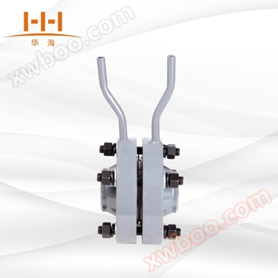
Balanced flowmeter is a revolutionary differential pressure flow meter, which works on the same principle as other differential pressure flow meters, based on the energy conversion principle in sealed pipelines: under ideal fluid conditions, the flow rate in the pipeline is proportional to the square root of the differential pressure; The flow rate in the pipeline can be calculated based on the Bernoulli equation using the measured differential pressure value. The balanced flow sensor is a porous disc throttling rectifier installed on the cross-section of the pipeline, with each hole's size and distribution customized based on special formulas and test data, known as a function hole. When the fluid passes through the function hole of the disk, it will be balanced and rectified, the vortex will be minimized, and an approximate ideal fluid will be formed. Through the pressure measuring device, a stable differential pressure signal can be obtained, and the volume flow rate and mass flow rate can be calculated according to the Bernoulli equation.
 |
1. Apply pressure to the flange;
2. Balance throttling components;
3. Metal wrapped gasket;
4. High and low pressure tapping pipes;
5. Signage
6. Elastic cushion;
7. Nut;
8. Flat pad;
9. Bolt
|
|
 |
1. Body welding forgings;
2. Balance throttling components;
3. High and low pressure tapping pipes
|
|
|
1. Flanges;
2. Measurement catheter;
3. Balance throttling components;
4. High and low pressure tapping pipes
|
 |
|
 |
|
High linearity and good repeatability
The balanced flow sensor has the characteristics of a symmetrical porous structure, which can balance the flow field, reduce eddy currents, vibrations, and signal noise. The stability of the flow field is greatly improved, and the linearity is increased by 5-10 times compared to the standard orifice plate. The repeatability is increased by 54%, which is 0.15%.
Low requirements for straight pipe sections
Due to the stable flow field and pressure recovery twice as fast as the orifice plate, the requirements for the straight pipe section of the balanced flow sensor are greatly reduced. The front and rear straight pipe sections are generally 3D and 1D, and the minimum can be less than 0.5D.
● Reduce permanent pressure loss
The porous symmetrical balance design reduces the formation of turbulent shear forces and eddies, and lowers the loss of kinetic energy. Under the same measurement conditions, the permanent pressure loss is 1/3 to 1/4 of that of the orifice plate, thereby saving considerable operating energy costs.
● Resistant to dirt and easy to block
The porous symmetrical balance design reduces the formation of turbulent shear forces and eddies, greatly reducing the formation of dead zones, ensuring the smooth passage of dirty media through multiple holes, and reducing the chance of fluid holes being blocked.
● Can directly replace the orifice plate
It has the same usage method and appearance as the orifice plate, so it can be directly replaced without any changes in piping or related instruments. It is very suitable for the energy metering transformation of the entire plant to replace the orifice plate with a balanced flow meter.
● Wide range ratio
Under normal circumstances, the range ratio of a balanced flowmeter is 10:1, and selecting appropriate parameters can achieve a wider range; The beta value can be selected from 0.25 to 0.90. Its performance allows its flow velocity to range from the minimum to the speed of sound; Its minimum Reynolds number can be lower than 200, and its maximum Reynolds number is greater than 107;
● Good long-term stability
Due to the significant reduction in turbulent shear force, the direct friction between the medium and the throttling element is greatly reduced, and its β value remains unchanged for a long time. The entire instrument has no movable parts, so it can maintain stability for a long time.
● Measurable high-temperature and high-pressure media
Like orifice plates and other throttling devices, the working temperature and pressure depend on the material and grade of the pipeline and flange. The working temperature can reach 850 ℃ and the working pressure can reach 42MPa.
● Measurable complex working condition media
Due to its unique structural design, it has special properties and can perform gas-liquid two-phase, various mixed gases (such as gas, biogas, coal gas, etc.), various low-temperature gases (such as LNG, liquid nitrogen, liquid oxygen, liquid argon, liquid hydrogen, liquid chlorine, liquefied ethylene, liquefied petroleum gas, etc.), gas-liquid two-phase media (such as moisture), slurry, multiphase water flow, vibrating water flow, electromagnetic interference media, and bidirectional flow (because the balance flowmeter is completely symmetrical on both sides).
The integrated structure is easy to use, inspect, and troubleshoot.
|
 |
|
● Pipe diameter range: DN15~DN1000 (large diameters can also be achieved)
Accuracy: ± 0.3%, ± 0.5%, ± 1%;
● Requirements for straight pipe section: 0.5D~2D;
Permanent pressure loss: 1/3 to 1/4 of the orifice plate;
Range ratio: 10:1, suitable operating data can achieve a wider range;
● Repeatability: 0.1%;
Reynolds number range: Re 200~107;
● β range: 0.25~0.9;
● Temperature range: The temperature that metal pipelines can withstand, up to 850 ℃;
Pressure range: The pressure that metal pipelines can withstand, up to a maximum of 42MPa;
● Stain resistance: special design and calculation;
Measurement of bidirectional flow: The balanced flow meter is completely symmetrical on both sides.
|
 |
|
The specific dimensions of pipeline type balance flow sensors and clamp type balance flow sensors are determined based on the customer's required pressure rating, specified flange standards, and on-site pipeline dimensions.
Welding type balanced flow sensor
|
 |
| caliber |
L |
¢B |
| DN15-DN40 |
160mm |
Based on the pipeline size and pressure rating requirements provided by the customer. |
| DN50-DN150 |
200mm |
| DN200-DN250 |
220mm |
| DN300-DN350 |
240mm |
| DN400-DN450 |
260mm |
| DN500 |
300mm |
|
|
 |
| model |
Instructions |
| HLGD-PH |
Balanced flow meter |
| |
code name |
Classify by structural form (mandatory) |
| |
PP |
pipeline-style |
| |
FW |
welded type |
| |
HF |
Clamping type |
| |
code name |
Nominal pressure (MPa) (mandatory) |
| |
2.0 |
2 .0 |
| |
5.0 |
5.0 |
| |
11 |
11 |
| |
26 |
26 |
| |
42 |
42 |
| |
code name |
Caliber (required) |
| |
15-1000 |
DN15-DN1000 |
| |
code name |
Media (required) |
| |
1 |
liquid |
| |
2 |
gas |
| |
3 |
steam |
| |
code name |
Compensation form (optional) |
| |
N |
Without temperature and pressure compensation |
| |
P |
With pressure compensation output |
| |
T |
Equipped with temperature compensation output |
| |
code name |
Differential pressure range of transmitter (optional) |
| |
0 |
Micro differential pressure range |
| |
1 |
Low differential pressure range |
| |
2 |
Medium differential pressure range |
| |
3 |
High differential pressure range |
| |
code name |
Whether to include on-site display (optional) |
| |
W |
Throttle device sensor |
| |
L |
Intelligent throttling device (flowmeter) |
|
 |
|
1. Pipeline: diameter, wall thickness, pipeline material
2. Measuring medium
3. Medium temperature (℃)
4. Working pressure of medium (MPa): maximum pressure, normal pressure, minimum pressure
5. Medium working flow rate: maximum flow rate, normal flow rate, minimum flow rate
6. Flow units (Nm3/h, m3/h, kg/h)
7. Medium viscosity (mPa. s)
8. Medium density (kg/m3)
9. Function Hole Algorithm: Four hole equal distribution, 1 hole+6 holes equal distribution, 1 large hole+6 holes equal distribution, 1 hole+8 holes equal distribution, 1 hole+10 holes equal distribution, 1 hole+12 holes equal distribution
|
 |
|
Before installation, the number, tag number, and specifications of the balance flowmeter should be checked to ensure they match the pipeline conditions, flow range, and other parameters.
2. When setting up a new pipeline system, it is necessary to first flush and clean the lines before installing the orifice plate to prevent debris from blocking or damaging the orifice plate inside the pipeline.
3. The center of the balancing throttling element should be coaxial with the center of the pipeline, and the coaxiality error should not exceed ± 0.015 * (1/β) -0.015. And the plane of the throttling end should be perpendicular to the pipeline, with an error not exceeding ± 1 °.
When installing a balanced flowmeter, the gasket must not protrude into the inner wall of the pipeline after clamping.
5. The installation of the balance flowmeter must be tight and there must be no leakage. After installation, conduct a pressure test.
6. The pressure conduit should be laid vertically or obliquely, with an inclination of not less than 1:12. The inclination of fluids with higher viscosity should be increased. When the transmission distance of the differential pressure signal exceeds 3 meters, the pressure pipe should be inclined in sections and installed at the highest and lowest points respectively
Gas collector and settler.
7. If valves need to be installed before and after the balance flowmeter, it is best to choose gate valves and fully open them during operation; The regulating valve should be located in the downstream pipeline after 5DN.
8. The pressure pipeline should be supported by sturdy brackets, and the two pressure pipelines should be as close to each other as possible and away from heat sources or vibration sources. When measuring water vapor flow, insulation materials should be used to wrap them together, and if necessary (such as temperatures below 0 ℃), heat tracing pipes should be added to prevent freezing. When measuring dirty flow rate, an isolator or settler should be attached.
When measuring liquid flow rate, the horizontal section of the pressure pipe should be in the same horizontal plane. If throttling devices are installed on vertical pipelines, a certain distance (perpendicular direction) between the short pressure pipes will affect the zero point of the differential pressure transmitter, which should be corrected through "zero point migration".
The inner diameter of the pressure pipeline is related to the length of the pipeline and the degree of contamination of the medium. Usually, pipes with an inner diameter of 8-12mm are used within 45 meters.
11. The pressure pipeline must always maintain a single-phase fluid state. When the measured fluid is a gas, the entire pressure pipeline (including the pressure chamber of the differential pressure gauge) is in the gas phase; When the measured fluid is a liquid, the entire pressure pipeline is in liquid phase and there must be no bubbles. For this reason, a drainage valve should be installed at the lowest point of the pressure pipeline or an exhaust valve should be installed at the highest point. Special attention should be paid when installing or repairing differential pressure transmitters.
When installing a balanced flowmeter on a vertical pipeline, the position of the pressure tapping port can be arbitrarily selected on the plane of the pressure tapping device. When the orifice plate is installed horizontally or obliquely in the main pipeline, the pressure port position is shown in (Figure 4).
|
 |
|
When the measured fluid is liquid or vapor
|
When the measured fluid is a gas
|
 |
1. Throttle device;
2-Valve;
3- Setter;
4- Differential pressure gauge;
5-Gas collector
|
 |
1. Throttle device;
2-Valve;
3-Isolator;
4- Setter;
5- Differential pressure gauge;
6-Gas collector
|
|
| |
 |
1. Throttle device;
2-Valve;
3-Isolator;
4-Gas collector;
5- Differential pressure gauge
|
|
 |
1. Throttle device;
2-Valve;
3-Blowing valve;
4- Setter;
5- Differential pressure gauge
|
|
 |
1. Throttle device;
2-Valve;
3-Isolator;
4- Differential pressure gauge;
5-Setter
|
|
 |
1. Throttle device;
2-Valve;
3- Insulation layer;
4- Setter;
5- Differential pressure gauge;
6-Gas collector
|
|
 |
1. Throttle device;
2-Valve;
3- Insulation layer;
4- Setter;
5- Differential pressure gauge;
6-Gas collector
|
|
 |
|
(1) Can be installed horizontally, vertically, or diagonally, ensuring that the pipe is filled with medium;
(2) The front and rear straight pipe sections of the throttling device should be straight, without visible bending to the naked eye, and should be "round". The inner wall should be clean, without pits or sediment;
(3) The length requirements of the straight pipe section and the installation of the throttling device shall comply with the relevant provisions of GB/T2624-93;
(4) The installation of pressure pipelines should comply with the specifications specified in the standards.
|
 |
| Fault phenomenon |
root cause |
Solution |
| No differential pressure signal output |
The high and low pressure valves are not open |
Open the high and low pressure valves |
| The balance valve is not tightened |
Tighten the balance valve |
| Differential pressure signal output too small |
Differential pressure range mismatch |
Adjust the transmitter range |
| Leakage of high-pressure impulse pipe |
Find and eliminate leaks |
| Differential pressure signal output too large |
Low pressure impulse pipe blockage |
Clean the pressure pipe |
| Differential pressure range mismatch |
Adjust the transmitter range |
|
 |
|
Comes with attachments
Pressure pipe, connecting flange, bolt, gasket, measuring conduit
Optional attachments
Paired flange and bolt gasket, condenser, socket welded gate valve, three valve group, needle valve, gas collector, isolator, and settler.
Optional related products
Pressure transmitter, temperature transmitter, flow meter integrator, intelligent differential pressure transmitter.
|
 |
 |
 |
 |
|
|
 |
 |
 |
| |
| |