
VIP member
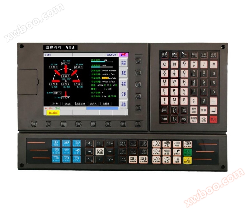
Convex Wheel CNC System 630TA
The seven axis cam walking machine CNC system is a specialized CNC system independently developed by Foshan Micro Control Industrial Automation Techno
Product details
Convex Wheel CNC System 630TA This system uses a 32-bit high-performance CPU and a large-scale programmable chip FPGA, with real-time control and hardware interpolation technology to ensure high efficiency at μ m level accuracy. The editable PLC


Make the logic control function more flexible and powerful. Replacing Yitu CNC system, manufacturer of convex wheel CNC system, price of convex wheel CNC system, brand of convex wheel CNC system
How to choose a manufacturer for convex wheel CNC system?
The cam centering/cutting machine CNC system is used to transform existing cam centering/cutting machines, directly controlling each tool with CNC, saving the huge trouble caused by redesigning the cam for different products and processes.
2. The CNC system of the cam centering/cutting machine can control 5 knives, 2 drill bits, or 1 tap and 1 die. Complex parts can be synchronously processed for external circle, spherical surface, conical surface, circular arc surface, step, cutting groove, rolling, drilling, tapping, die, cutting and other processes. The entire process can be completed in one machining step.
3. M2 bus communication, multi axis linkage, and precision control of each axis can reach 0.001mm.
4. Support various diversified feeding institutions.
Features of the 630TA Convex Wheel CNC System: What is a Convex Wheel CNC System?
Number of control axes: 7 feed axes, 2 simulated spindles;
Number of linkage axes: 5 axes
8-inch widescreen LCD with a resolution of 800 × 480
Adopting 32-bit high-performance CPU and ultra large scale programmable device FPGA
56M user storage space
Real time all-round self diagnostic function, displaying various system statuses in real-time
Feed per minute, feed per revolution

Metric and British input methods
Machine tool returns to reference point
Rapid magnification: F0, 25%, 50%, 100%, a total of four levels for real-time adjustment
Feed rate: 0-150%, a total of sixteen levels of real-time adjustment
1-way spindle encoder feedback, the number of spindle encoder lines can be set (100p/r~5000p/r)
Transmission ratio between encoder and spindle: (1-255): (1-255)
Spindle speed: can be given by S code or PLC signal, with a speed range of 0r/min to 9999r/min
Spindle ratio: 50% to 120%, with a total of 8 levels of real-time adjustment
Interpolation methods: Linear interpolation, arc interpolation (supports three-point arc interpolation)
Spindle constant linear velocity control
ISO code, supports statement macro code programming, supports relative coordinate, absolute coordinate, and mixed coordinate programming
Program Call: Supports macro program calls with parameters and nested 4-level subroutines
Handwheel Teaching Table Programming
Independent reverse clearance compensation for each axis
Pitch error compensation: The number of compensation points, compensation interval, and compensation origin can be set
Tool radius compensation, tool length compensation, tool wear compensation, tool life management
Knife deviation execution method: modify coordinate method, tool movement method
Maximum speed and independent acceleration/deceleration settings for each axis
Emergency stop, hardware travel limit, software travel check
Switching between Chinese and English pages
Display real-time time, number of processed items, processing time and other information
Various interpolation instruction functions and M, S, T functions, etc

Online inquiry
-
Contacts
-
Company
-
Telephone
-
Email
-
WeChat
-
Verification Code
-
Message Content
-