
VIP member
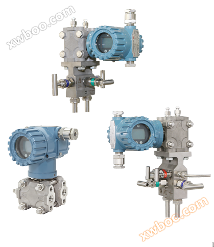
361D series monocrystalline silicon differential pressure transmitter (accuracy up to 0.065%)
Used for measuring flow rate, liquid level, and pressure; By adopting HART fieldbus technology, more on-site information can be provided to improve th
Product details
performance index
The overall performance is based on the comprehensive error of reference accuracy, environmental temperature influence, and range static pressure influence.
Accuracy index
± 0.04-0.075% FS range
stability
≤± 0.2% FS/5 years
Specific performance indicators
Zero based range, reference conditions, silicone oil filling, 316 stainless steel isolation diaphragm, 4-20mA analog output, digital fine adjustment value equal to the range set point value. )
accuracy
(Reference accuracy includes hysteresis, terminal based linearity, setting capability, and repeatability)
± 0.04-0.075% range
If the range is less than X
±[0.015+0.05 ]%
]%
]%X value:

Static pressure effect
± 0.15%/10MPa upper range limit
Zero point impact
The zero position can be adjusted on-site according to the installation location, or the pressure zero position can be relocated.
Damping time constant
The total damping time constant is equal to the sum of the damping time constants of the amplifier component and the diaphragm box. The damping time constant of the amplifier component can be adjusted within the range of 0-100 seconds.
Membrane box (silicone oil)
Time constant (seconds) (can be set according to the actual situation on site, recommended 1 second)
Installation location impact
Changes in installation position parallel to the membrane surface will not cause zero drift effects. If the installation position changes by more than 90 degrees from the membrane surface, within the range of 0.4KPa
Zero drift can be corrected by zero adjustment without affecting the range.
Power supply impact
Less than ± 0.005% range/volt
Functional indicators
Range and Sensor Limit Values
Table 1.361D transmitter range and sensor limit values

Zero point and range adjustment requirements
·The zero point and range can be adjusted arbitrarily within the range limits indicated in Table 1.
·The range must be greater than or equal to the minimum range indicated in Table 1
Application scenarios
Measurement occasions for liquids, gases, and vapors
output
Two line 4-20mA, users can choose linear output or square root output. The digital process variable is superimposed on a 4-20mA signal and is suitable for any host that complies with the HART protocol.
power supply
External power supply is required. The standard transmitter (4-20mA) operates at 14.5-45V DC when unloaded.
Circuit load limit
The maximum circuit resistance is determined by the external power supply voltage, and the relationship is as follows:

Note: The power supply voltage range for transmitters with backlit display screens is 14.5-45V
The power supply voltage range of intrinsic safety series transmitters is 14.5-28V
The working voltage during HART communication should be greater than 17.5V
Fault mode
output code
When a fault is detected in the sensor or microprocessor during self diagnosis, the transmitter drives the output of a high or low alarm signal to alert the user. ALARM IN
The value depends on the factory configuration of the transmitter:
Linear output: 3.8<I<20.8
C4: I=20.8mA fault high
CN: I=3.8mA fault low
Temperature Limit
environment
-20 ℃ to+70 ℃ (normal)
-40 ℃ to+85 ℃ (maximum)
-40 ℃ to+85 ℃ (maximum)
keep in storage
-46℃~110℃
With header: -40 ℃~85 ℃
process
At atmospheric pressure greater than or equal to, see the table below
Table 2.361D transmitter process temperature limit

temperature drift
≤0.065%FS/10℃
Humidity limit
0-100% relative humidity
Start Time
The transmitter reaches its performance indicators within 2 seconds of being powered on
Mechanical performance indicators
electrical interface
ANSI (American Standard) NPT1/2 (F) internal thread
ISO M20 × 1.5 internal thread
process interface
No process joint (NPT1/4 internal thread on chamber flange)
With "waist" shaped connector: NPT1/2 cone tube internal thread
With "T-shaped" joint: M20 × 1.5 external thread and rear welded pressure pipe (stainless steel)
Equipped with a "waist" shaped joint and NPT1/2 pressure crossing head and rear welded pressure pipe (stainless steel)
Process liquid receiving components
Process isolation membrane: 316L stainless steel, Hastelloy C
Drain/exhaust valve
316 stainless steel
Process flanges and joints
Carbon steel plated with cadmium, 316 stainless steel
Non liquid parts
Electronic housing
Die cast aluminum IP65
coating
Powder coating
Cover O-ring
Nitrile rubber
• Adopting MEMS monocrystalline silicon high-precision pressure sensor
Fast response speed and high stability
• Measurement accuracy 0.04-0.075% FS
The maximum range ratio can reach 100:1
Adopting dual overload protection technology
Strong overload capacity, unidirectional pressure can reach 10MPa
The maximum static pressure can reach 10MPa
• Provide standard HART bus communication mode
• Comprehensive self diagnosis and remote communication functions
LCD display with backlight and high brightness
• 360 degree rotatable on-site display screen
• Convenient on-site reset function
Convenient on-site zero and full point setting and calibration functions
Convenient on-site current circuit verification function
Online inquiry
-
Contacts
-
Company
-
Telephone
-
Email
-
WeChat
-
Verification Code
-
Message Content
-